ABSTRACT
The electricity sector is undergoing an evolution that demands the development of a network model with a high level of intelligence, known as a Smart Grid. One of the factors accelerating these changes is the development and implementation of renewable energy. In particular, increased photovoltaic generation can affect the network’s stability.
One line of action is to provide inverters with a management capacity that enables them to act upon the grid in order to compensate for these problems. This paper describes the design and development of a prototype embedded system able to integrate with a photovoltaic inverter and provide it with multifunctional ability in order to analyze power quality and operate with protection. The most important subsystems of this prototype are described, indicating their operating fundamentals.
This prototype has been tested with class A protocols according to IEC 61000-4-30 and IEC 62586-2. Tests have also been carried out to validate the response time in generating orders and alarm signals for protections. The highlights of these experimental results are discussed. Some descriptive aspects of the integration of the prototype in an experimental smart inverter are also commented upon.
DESCRIPTION OF THE SYSTEM
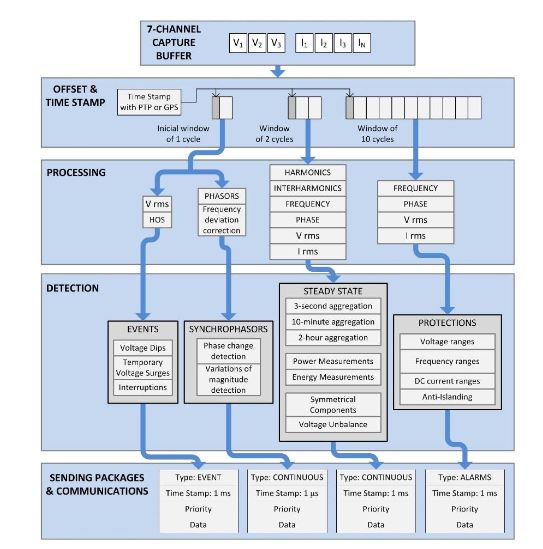
Figure 3. Functional architecture for the developed ES
Moreover, all of the stationary power quality parameters are associated with the 10-cycle windowing, obtaining aggregations of greater duration, according to parameters and needs. Finally, the data are classified and packaged in such way that it can be communicated to other devices or network entities. The frame structure has fields for classification, time stamping and priority. Figure 3 presents the architecture of the ES developed, with a scheme of the functionality, as well as the three processing routes.
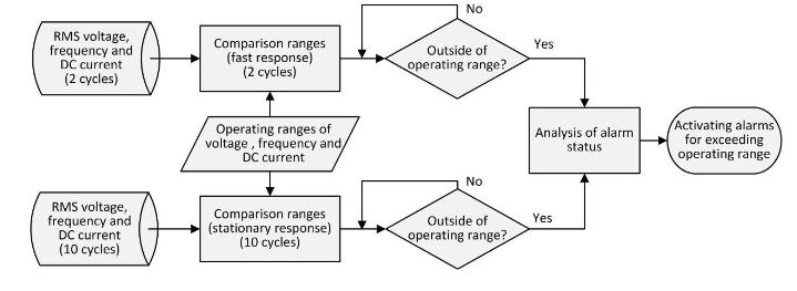
Figure 5. Alarms generation algorithm for exceeding operating ranges of voltage, frequency and DC current injection
The standards used in this subsystem are IEC 61727, VDE 0126-1-1, IEEE 1547 and IEEE 929. As already mentioned, the system presented here enables new regulatory changes to be introduced easily. The algorithm in Figure 5 checks whether the voltage, frequency and DC current injection are within the operating windows. If not, it generates alarm signals directed to the maneuver
TESTING AND EXPERIMENTAL RESULTS
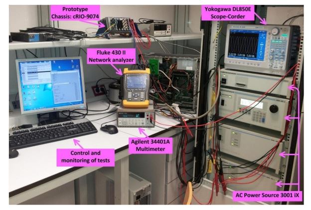
Figure 9. Test context and equipment
To contrast the measurements taken with the prototype, a 430 II analyzer grid (Fluke Corporation, Everett, WA, USA) and a 34401A multimeter (Agilent, Santa Clara, CA, USA) with 6 ½ digits, was used together with a DL850E ScopeCorder oscilloscope-recorder (Yokogawa Electric Corporation, Tokyo, Japan). In all tests a nominal reference voltage of 230 V was used. The series of measurement data on the prototype have been built with a 5-minute observation period, samples being taken every 200 ms. Figure 9 shows an image of the scene the testes.
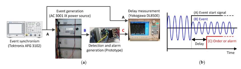
Figure 17. Time response tests: (a) Tests context; (b) Signals for delay measurement
The purpose of these tests is to measure the time between the occurrence of the event and the generation of the alarm signal. The setting of the test is shown in Figure 17. An external sync signal is used to trigger the event with the programmable source. Once the prototype detects the nature of the event, it will trigger the alarm or order signal being analyzed.
INTEGRATING OF THE EXPERIMENTAL PROTOTYPE INTO A PHOTOVOLTAIC INVERTER
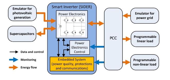
Figure 20: Test context for SIDER smart inverter
This project is based on the development of an inverter with active management capacity within a Smart Grid environment. The present ES was developed under the PROCOM-SIDER subproject, reference code TEC2010 19242-C03-02, whose purpose was to provide the inverter with a parameter and events analysis functionality, as well as protection and communication, according to the scenario depicted in Figure 20.
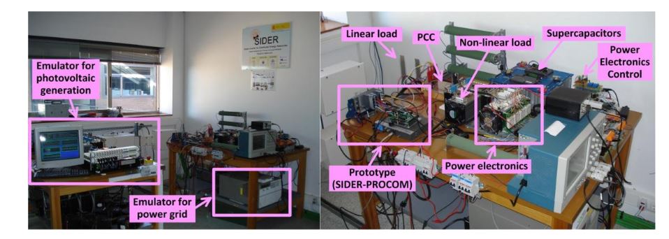
Figure 21. Experimental environment for the SIDER smart inverter
Although the tests conducted in prototype confirmed its good behavior, the SIDER experience has served to confirm the proper functioning of ES within a cont ext of real integration. Figure 21 shows the final result of integrating the prototype during the tests within the SIDER context.
CONCLUSIONS
This paper has presented the design and development of a prototype multi-functional ES for controlling and managing the interface between a smart inverter and the electricity grid in a Smart Grid context. The design has focused upon the appropriate timing requirements for measurements defined in IEC 61000-4-30. These requirements have led to a data architecture design based on a set of critical temporary loops, where the various groups of equipment functions are processed: A half-cycle loop that directly processes the data acquisition for transient events or those of a highly random nature.
A two-cycle loop, which has been implemented on this equipment in an original manner, which the team has termed quasi-stationary is used for rapid measurements with some stationarity, where the protection functions are processed. Finally, a 10-cycle loop dedicated to processing functions of purely stationary power quality parameters. The data exchange is carried out by two deterministic FIFO stacks, managed from the fastest half-cycle loop, and synchronized to two and ten cycles. It is important to emphasise the great functional capacity of the prototype at the Power Quality level, where it is able to endow the inverter with great added value, transforming it Power Quality Analyzer (PQA).
In order to do this, ultimate-generation event-detection algorithms, such as those based on Higher-order statistics (HOS), have been incorporated, as well as other, original algorithms for passively detecting is landing, based upon multiple-method weighting. The equipment has been subjected to Class A and Class S testing procedures, according to standard IEC 62586-2, obtaining good results in all of the tests whose conditions were within the limitations of our laboratory resources.
Unfortunately, due to these limitations it was impossible to address all test scenarios, so it cannot be concluded that the equipment can be considered Class A, but everything indicates that it could pass a rigorous certification of this kind. In addition, based on the tests of uncertainty in measurements and temporary response to alarms, a positive validation in system behavior can be concluded. Furthermore, its proper functioning under the SIDER project, sponsored by the Ministry of Science and Innovation of Spain and supervised by companies in the electricity sector, where the prototype’s suitability for being integrated into the power electronics of a photovoltaic inverter has been proven.
Source: University of Cordoba
Authors: Rafael Real-Calvo | Antonio Moreno-Munoz | Juan J. Gonzalez-De-La-Rosa | Victor Pallares-Lopez | Miguel J. Gonzalez-Redondo | Isabel M. Moreno-Garcia