EXECUTIVE SUMMARY
Commuter parking at the University of Tennessee, Knoxville can be a frustrating experience, due especially to the imbalance between commuter students and commuter parking spots. There are considerably more commuter passes than there are commuter spots, thus requiring most students to arrive on campus much earlier and causing large amounts of traffic during class transitions. Currently, there are very few resources to help alleviate this problem, thus a solution would be highly desirable by UT students.
The Campus Parking Availability System (CPAS) aims to relay data to students, showing the occupancy of each parking lot. The system provides a website interface for the student, who can make decisions for parking based on the available data. The design of the system consists of three different sections: on-site, off-site, and the website interface. The on-site system consists of a pair of ultrasonic systems at each entrance/exit of a parking lot. These sensors are connected to a Raspberry Pi, a small linux-capable single board computer, with Wi-Fi capabilities. The sensors monitor entering and exiting vehicles to maintain a current count, which the Raspberry Pi will send to a central server every minute.
The off-site system is composed of the central server and the database. The central server receives data from every Raspberry Pi in the system and stores the information in the database. The server is also responsible for establishing and maintaining a connection with each on-site system. The website interface accesses the database to display the most current information from the system to the user. The website is configured to be convenient for desktop, mobile, or tablet device usage. Graphs and analytics are then performed on the historic data to provide trend lines and predictive analytics. The biggest challenge of the project was discovering and fixing the physical limitations of our ultrasonic sensors.
Our initial set of sensors functioned differently than what was expected, which required some research to find suitable replacements. After installing these sensors in the prototype location, the readings revealed interference between the two ultrasonic pulses. This problem was removed by controlling when each sensor took a reading, and thus synchronizing the readings such that neither sensor fired while the other was reading. Overall, CPAS has met a majority of the proposed requirements and goals that were created at the start of the Fall 2014 semester.
CHANGE LOG
– Removal of Android/iPhone mobile application requirement
– Relaxation of accuracy requirements for lot occupancy measurements
– Addition of necessary power supply requirement
– Simplification of analytics requirement
DOCUMENTATION OF DESIGN PROCESS
The final design of the CPAS system is a culmination of two semesters worth of investigation, testing, and modification. In order to design a system that fulfills the standards set by the team’s customer, Dr. Mark Dean, and the Requirements document, it was essential to divide project tasks evenly amongst each team member.
Because the CPAS project was a continuation from the Fall 2014 semester, much of the research regarding potential solutions had already taken place and been documented in papers from COSC/ECE 401. A significant amount of the research leading up to the Spring 2015 semester was devoted to finding and selecting a sensor type that would enable our system to provide accurate, reliable vehicle tracking. On top of providing suitable tracking capability, our selection of sensor type would hinge on whether or not that sensor family could feasibly operate in both indoor and outdoor environments.
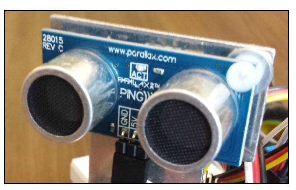
Figure 1. HC-SR04 Ultrasonic Sensor
Following initial investigation of MAXBOTIX models, Dr. Dean was able to supply us with two MB-7092 sensors that he had in his possession, and these are the sensors we selected for prototyping. The sensor itself operates by taking distance measurements via sonar emissions and bases data readings on the amount of time it takes for given pulses to be reflected back. It also uses the magnitudes of these reflections to discern object size.
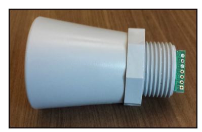
Figure 2. MAXBOTIX MB-7092 Weather Resistant Ultrasonic Sensor
PROTOTYPING
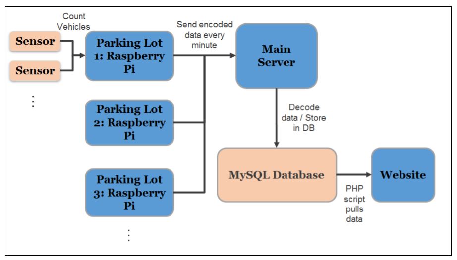
Figure 5. Solution Outline
Following meetings with UT Facilities Services, the Office of Information Technology (OIT), and the Finance and Administration Division, we had a number of options in terms of which parking lot or garage would be the test bed for the initial controller-sensor network. To have the best shot at meeting semester goals and actually implementing our system.
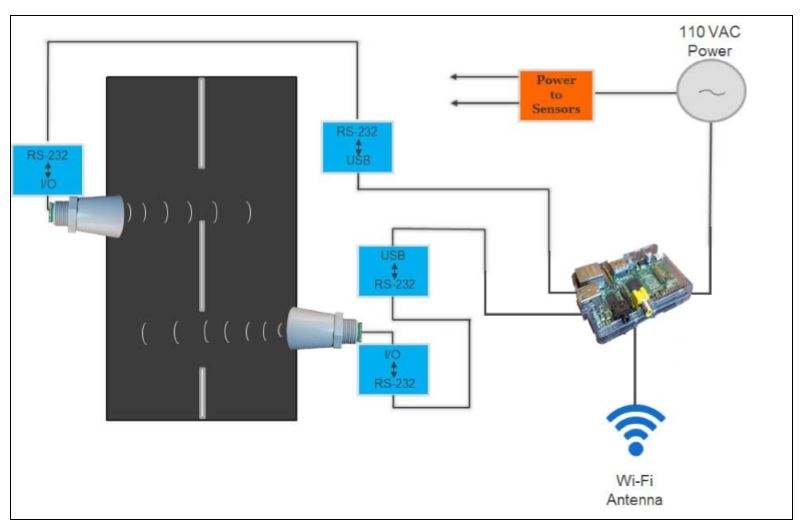
Figure 6. On-Site System Design
CPAS required the installation of the selected sensors at each parking entrance/exit, in order to accurately measure the quantity of incoming/outgoing vehicles. The configuration of these sensors is set based on on-going testing efforts. These sensors are connected to a Raspberry Pi, which is connected to a continuous 110 VAC wall outlet. Future implementations of this system will attempt to utilize more mobile power sources, such as batteries, solar panels, etc. The Pi interfaces with the sensors to translate signals into the relevant data.
FINAL LIST OF MATERIALS
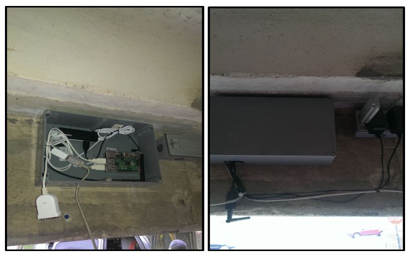
Figure 8. Main box holding the Raspberry Pi
Figure 8. Main box holding the Raspberry Pi, Wi-Fi Antenna, USB Hub, and cable slack. Stowed in the upper lip of garage entrance next AC to wall outlet.
LESSONS LEARNED
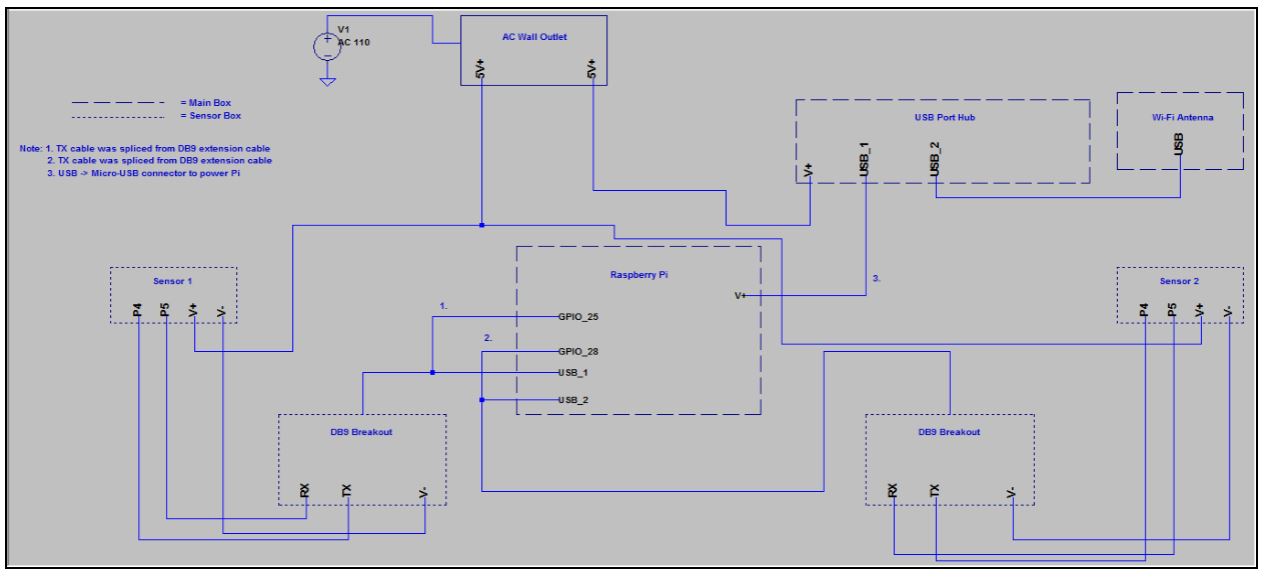
Figure 10. Schematic of the on-site system
Our initial tests in the Senior Design lab showed no sign of signal interference between the two sensors. Once the sensors were installed in the parking garage we began to notice that we were getting errant readings. However, these readings did not occur until the day after the sensors were installed ( about 24 hours later). After numerous tests, we determined that the sensors were beginning to conduct range readings with slightly different frequencies, and this frequency drift caused interference between the two sensors. Each sensor was operating at a different timing interval.
Source: University of Tennessee
Author: Jacob Lambert