ABSTRACT
Falls are a major health risk with which the elderly and disabled must contend. Scientific research on smartphone-based gait detection systems using the Internet of Things (IoT) has recently become an important component in monitoring injuries due to these falls. Analysis of human gait for detecting falls is the subject of many research projects.
Progress in these systems, the capabilities of smartphones, and the IoT are enabling the advancement of sophisticated mobile computing applications that detect falls after they have occurred. This detection has been the focus of most fall – related research; however, ensuring preventive measures that predict a fall is the goal of this health monitoring system. By performing a thorough investigation of existing systems and using predictive analytics, we built a novel mobile application/system that uses smartphone and smart – shoe sensors to predict and alert the user of a fall before it happens.
The major focus of this dissertation has been to develop and implement this unique system to help predict the risk of falls. We used built – in sensors — accelerometer and gyroscope — in smartphones and a sensor embedded smart – shoe. The smart – shoe contains four pressure sensors with a Wi – Fi communication module to unobtrusively collect data. The interactions between these sensors and the user resulted in distinct challenges for this research while also creating new performance goals based on the unique characteristics of this system. In addition to providing an exciting new tool for fall prediction, this work makes several contributions to current and future generation mobile computing research.
BACKGROUND AND OVERVIEW OF CURRENT TECHNOLOGIES
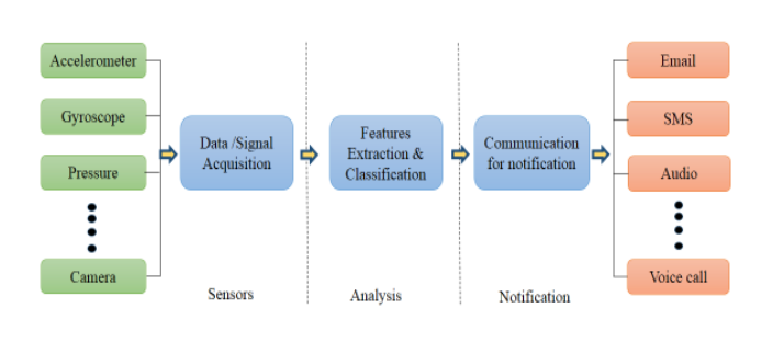
Figure 1 . Basic architecture of smartphone – based systems.
Fall detection and fall prevention systems have the same basic architecture as shown in figure1. These systems follow three phases of operation: sense, analysis, and communication. The main difference between these systems lies in their analysis phase, which varies in their feature extraction and classification algorithms. Fall detection systems try to predict the occurrence of falls accurately by extracting the features from the output 12 data of the sensors and then identifying falls from other activities of daily living (ADL). Fall prevention systems can predict fall events early by analyzing the outputs of the sensors.
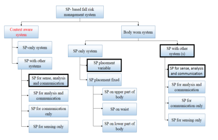
Figure 2. Taxonomy of smartphone – based systems based on sensing mechanism and sensor placement.
Figure 2 illustrates the taxonomy of smartphone – based fall detection and prevention technologies based on their sensing mechanisms and sensors placement. Existing solutions are represented with rectangles, while bold rectangles represent possible solutions that have not previously been reported to identify areas for future research. Smart phone – based solutions can be categorized into two types: context – aware and body – worn. With context -aware systems, the user should not wear any sensor or system.
Sensors are placed in the user’s surrounding environment and the user can move freely within the range of the sensors. Though, the main advantage of context – aware systems is that the person does not need to wear any special device, their operation is limited to those places where the sensors have been previously placed. No such smartphone – based context – aware solution has been found.
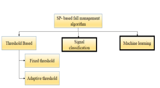
Figure 3. Taxonomy of smartphone based fall detection and prevention algorithms.
Smartphone – based solutions can also be categorized on the basis of algorithms used in the analysis phase. Figure 3 presents the taxonomy of these algorithms. Due to the lower processing capacity and low – energy storage capacity of batteries in smartphone compared to desktop or laptop computers, smartphone – based solutions mostly use TBAs for the detection of falls.
RESEARCH CHALLENGE IDENTIFICATION
Gait Abnormality Detection Using Smartphone Sensor Data
The benefits of using a smartphone as a pervasive fall detection and prevention system have already been discussed in the literature. Smartphone – based systems experience some critical challenges with certain issues remaining open to further research. These challenges and open issues in smartphone – based fall management systems have been identified; this section presents the most relevant ones.
LIMITATIONS OF SMARTPHONE SENSOR-BASED SYSTEMS AND DESIGN AND DEVELOPMENT OF A WIRELESS SMART-SHOE
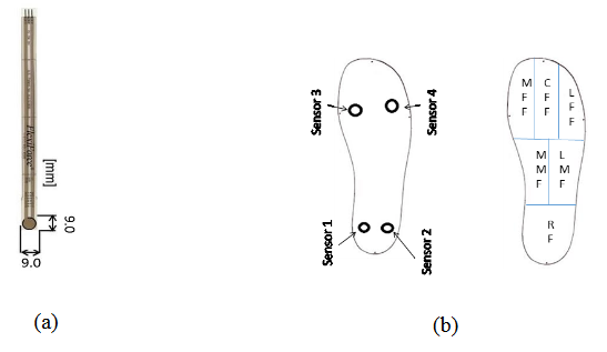
Figure 6 . (a) Piezoresistive Sensor (b) In-sole sensors distribution (Measurement Position).
The pressure sensors we employed in this system are SEN 08685, which are flexiforce force – sensitive resistor sensors. SEN 08685 sensor is a flexible printed circuit with thickness of 0.203 mm. Clearly the more sensors are placed, the higher precision of plantar pressure distribution can be measured. Our goal is to adjust the number of pressure measurement points. Most of body pressure is measured from the rear foot and the fore foot. Considering these issues we have placed two of our sensors in the fore foot region and two of them are in the rear foot region as shown in figure 6.
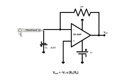
Figure 7. Amplifier circuit with pressure sensor.
The amplifier circuit, shown in figure 7, amplifies the output of the pressure sensor. Each sensor has its own amplifier circuit. The circuit is an inverting operational amplifier that produces an analog output based on the sensor resistance and a feedback resistance (RF = 10k). The sensor resistance (RS) at no load condition is greater than 5M ohm. The application of a force to the active sensing area of the sensor results in a change in the resistance of the sensing element inversely proportional to the force applied.
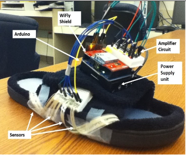
Figure 9a. Smartshoe hardware mounted on shoe.
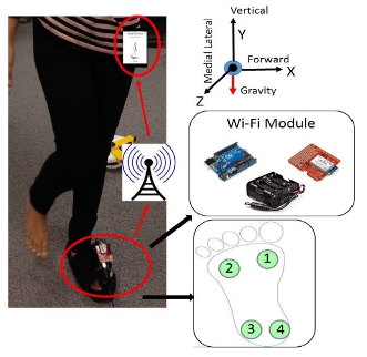
Figure 9b. IoT components of a wireless shoe with an example of the walking event trial in the hallway.
Using all of the electronics (including the sensors located at the bottom of the shoe), a wi- Fi module for the wireless transmission, and the power supply, we were able to engineer a smart – shoe as shown in figure 9a. Each shoe module consisted of an instrumented insole placed beneath the foot and an attachment that mounted to the back of the shoe. A sample insole of a smart – shoe and enclosed sensors and hardware are detailed in figure 9b.
DESIGN AND DEVELOPMENT OF A SMART FALL PREDICTION SYSTEM
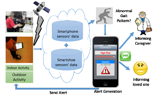
Figure 10. System architecture of proposed system.
This overall architecture was developed assessing iterative designs of the prototypes with three age ranges (25 – 35, 35 – 45, and 50+ years). To integrate the sensors, we used output of both the smart – shoe and smart phone and performed a set of experiments to analyze and discriminate between normal and abnormal walking patterns. Subjects wore the smartshoe like any other regular walking shoe and carried their smartphone in their pocket or held it in their hand.
DEVELOPMENT OF A GAIT LOGGER FOR DATA COLLECTION AND FEATURE EXTRACTION
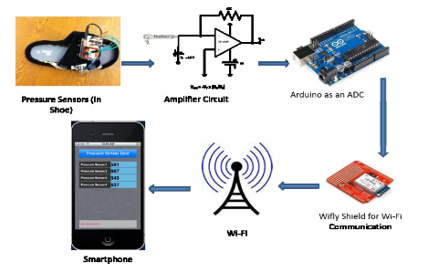
Figure 12. Data collection process from a smartshoe.
The smart – shoe data collection process is shown in figure 12. The pressure data from the shoe are transferred to the smartphone through an adhoc Wi – Fi communication network. Pressure data were collected for the test subjects over a period of time and each time subject was tested with standing and three different walking patterns.
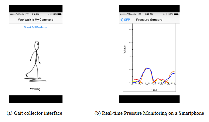
Figure 14. Screenshots of prototype system.
The screenshots of the system prototype application are shown in figure 14. In figure 14 (a), the gait collector interface is shown while walking. We can also monitor insole pressure variation with graphical representation on a smartphone which is shown is figure 14 (b). We used our prototype application for data collection and for evaluating our system.
EVALUATION AND ANALYSIS OF THE SYSTEM
![Figure 18. WEKA feature visualization tool and data analysis tool [93 ].](http://ece-eee.final-year-projects.in/wp-content/uploads/2017/11/p-2942-development-of-a-wireless-mobile-computing-platform-for-fall-risk-prediction.PNG11.png)
Figure 18. WEKA feature visualization tool and data analysis tool.
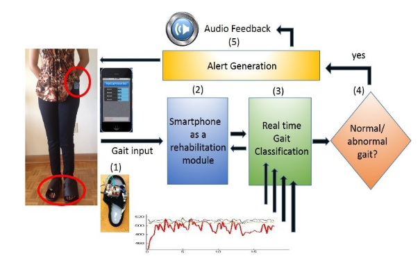
Figure 20. The Gait Detection system with its IoT components.
For our collected data, the classification accuracy was very good when considering two subjects in the training data, but was poor when attempting to classify one subject’s gait based on the other subject. To overcome this, we analyzed our collected data from the smart – shoe using a signal classification approach that is based upon modeling the dynamics of the system. We used a unique signal classification approach that models the dynamics of a system as they are captured in a Reconstructed Phase Space (RPS). The architecture of the system used for this analysis is shown in figure 20.
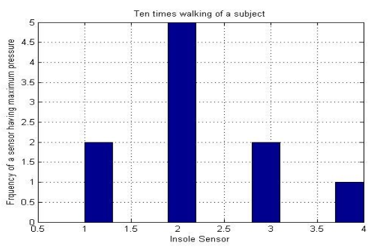
Figure 21. Histogram of maximum pressure variation for different subjects.
We used this maximum pressure value while determining the threshold for each subject in his or her walking pattern. We also saw the variations of different walking patterns for different subjects. Figure 21 is the histogram of maxi mum pressure variation count of ten times walking for a test subject. We observed that sensor two Heel (Hind foot) has maximum pressure for five times while walking.
CONCLUSION
In this dissertation we present a smartphone and smart – shoe – based mobile gait monitoring system that helps to predict a fall through real – time abnormality detection in users’ gait patterns. The system is the first smartphone – based application that uses the combination of built – in accelerometers and gyroscopes and pressure distribution from shoe instrumented with sensors to help predict a potential fall.
This research work has made several contributions to address the problem of smartphone – based low energy health monitoring system for current and next generation mobile computing. Since ensuring preventive measures is the common goal in almost any smartphone and smart – shoe – based risk management system, our major focus has been to develop and implement a cyber – physical system to solve the identified research issues using built – in sensors in smartphone and the sensor embedded smart – shoe. Our contributions include:
We have designed and developed a smartphone – based gait monitoring system using built – in smartphone sensors (e.g. gyroscope, accelerometer, and GPS). In this research, we detected abnormal walking patterns using only smartphone sensor data processed by the smartphone. The accelerometer and gyroscope of a smartphone were used to determine the abnormal gait pattern of the user. The GPS of the smartphone was used for location information of the user.
Source: Marquette University
Author: AKM Jahangir Alam Majumder
>> Top Sensor based IoT Projects for ECE Students
>> WiFi based IoT Projects for Engineering Students
>> 50+ IoT based Wireless/GSM Projects for Engineering Students
>> IoT based Real-Time Projects for B.E/B.Tech Students
>> 200+ IoT Led Projects for Final Year Students