ABSTRACT
In todays society, information is available to us at a glance through our phones, our laptops, our desktops, and more. But an extra level of interaction is required in order to access the information. As technology grows, technology should grow further and further away from the traditional style of interaction with devices. In the past, information was relayed through paper, then through computers, and in todays day and age, through our phones and multiple other mediums.
Technology should become more integrated into our lives – more seamless and more invisible. We hope to push the envelope further, into the future. We propose a new simple way of connecting with your morning newspaper. We present our idea, the SmartMirror, information at a glance. Our system aims to deliver your information quickly and comfortably, with a new modern aesthetic. While modern appliances require input through modules such as keyboards or touch screen, we hope to follow a model that can function purely on voice and gesture.
We seek to deliver your information during your morning routine and throughout the day, when taking out your phone is not always possible. This will cater to a larger audience base, as the average consumer nowadays hopes to accomplish tasks with minimal active interaction with their adopted technology. This idea has many future applications, such as integration with new virtual or augmented reality devices, or simplifying consumer personal media sources.
FUNCTIONAL REQUIREMENTS
The following requirements define the goals of the project outlined in the introduction. The functional requirements define features that must be done for the project to be considered a success, while the non- functional requirements define how the functional requirements are achieved. Requirements are categorized into critical, recommended, and suggested. Critical requirements are absolutely necessary, recommended are highly desirable, and suggested requirements are not necessary but would be very nice to add. Design constraints are criteria that the solution must adhere to. The constraints are set by the client and are non-negotiable.
- Functional Requirements
- Non-Functional Requirements
- Design Constraints
- Requirements Justification
USE CASES
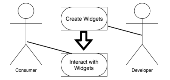
Figure 3.1: Use Case for Project.
Below are a few use cases for our platform. Use cases are examples of how our system is to be used. The main actors of our system are the consumer, who plans to interact with widgets, and the developer, who plans to create new widgets. Figure 3.1 displays our use case diagram for our system.
ACTIVITY DIAGRAM
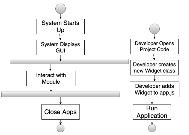
Figure 4.1: Activity Diagram for Consumer (left) and Developer (right).
The general work-flow of the planner can be graphically represented in an activity diagram. Figure 2 shows how an average user will use the SmartMirror, and the step by step process they will go through as they progress through the site. The diagram shows the work flow for all average users. The system will load the user GUI. The user is then able to interact with selected modules, or open new modules.
CURRENT MODEL
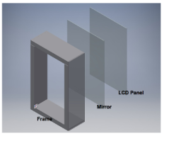
Figure 5.2: Outer Structure.
On the outside, the hardware is encapsulated within a wooden frame. On the front, a two-way mirror is placed in front of a LCD monitor. This way, the system can act as a mirror when not currently in use, while the LCD projects through the mirror when in use. The wooden frame has a bezel on the front which the mirror and LCD panel are pressed against. Cutouts for dowels are added in line with the back of the LCD panel to keep the components snug against the bezel.
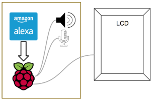
Figure 5.3: Inside.
Behind the LCD panel is the heart of the product, the Raspberry Pi, which is connected to the LCD for visual display. We also have a microphone and speaker attached for audio input and output. The Raspberry Pi runs our software and also allows us to connect to the Internet for web services, such as Amazon’s Alexa Voice Service.
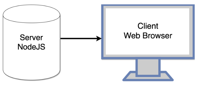
Figure 5.4: Application Structure.
The application makes use of two main sections – a server and a local client. The server, built using Node.js provides the back end for the project. The hosts a simple web page and opens a web browser directed to that page. The HTML content of the page contains the grid layout for widgets to be placed in. Tied to this web page is the local client, built using JavaScript. The local client communicates with the server and handles all display activities.
The client loads and refreshes widgets as needed and provides the primary interface for users. Using IPC, the Node.js server is able to send commands to the client in order to extend functionality. This can be used to communicate with other IoT devices and display data such as current temperature in a house as reported by a smart thermostat. The same could be done in reverse, where information is sent to an IoT device or Internet service.
ARCHITECTURAL DIAGRAM
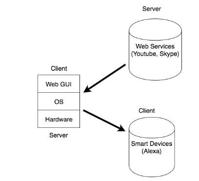
Figure 6.1: Architectural Diagram.
The design of the system is a combination of a layered architecture and a client-server architecture. The user interacts primarily with the GUI that is built upon the OS we use for the development for our system. When they attempt to make requests to edit their settings directly, they will be making a call as an application to the underlying OS, which will change the system accordingly. The system itself communicates with remote clients via the Internet.
TECHNOLOGIES USED
Below are a list of technologies we plan to use for our project. Being a web-based application, we used a variety of web tools:
- HTML
- CSS
- JavaScript
- NodeJS
- Electron
- GitHub
- Travis CI
- Raspberry Pi
- Amazon Alexa Voice Service
The primary hardware component for our system is the Raspberry Pi. In particular, we use the Raspberry Pi 3 as it maintains the same price point but offers additional processing power, more RAM, and offers onboard bluetooth and WiFi for connectivity. The Raspberry Pi was selected for its ease of use and availability to the hobbyist community. The Raspberry Pi is capable of running several flavors of Linux, all of which should be capable of running our software platform.
COSTS
In order for someone to replicate this project, they would be required to pay a similar up-front cost; however, many hobbyists may already own some of the necessary materials. Choosing commonly used hobbyist pieces makes the project most accessible to the widest audience and also helps decrease initial investment costs.
DESIGN RATIONALE
We decided to make our model open source, due to the fact that it allows a plethora of users to enjoy the product on different levels: the average user will not concern themselves with a difficult world of development, and the talented programmer will be able to modify the product to suit their needs. We feel that this supports and builds a healthy community, as all other marketed renditions on the market today do not allow for customization.
TESTING PLAN
In order to verify the functionality of the system, several rounds of testing is necessary. Testing at each stage of development ensures that errors are caught early and addressed before they cause delays in development and delivery.
- Alpha Testing
- Beta Testing
- Test Results
RISK ANALYSIS
For our risk analysis table, as seen in Figure 4, it is broken down into six different categories.
- Name of Risk
- Consequences
- Probability
- Severity
- Impact
- Mitigation Strategies
DEVELOPMENT PROCESS
Each team member is assigned tasks to help ensure project success. The legend above identifies which team member has which task, along with group tasks, and deadlines. While most of the group is working on tasks together, certain group members have been appointed leads on different areas, such as customer liaison, implementation lead, and testing lead. The timeline has been broken into four different sections: Requirements, Design, Implementation, and Testing.
For Requirements, this is divided into two parts. The first part is the initial requirements gathering from the client, during weeks 8 and 9. The requirements supplied by the customer help formulate our design idea. The second part, from weeks 8 through 7, is a period of customer interview and feedback on our product, to help mitigate the risk of failing to meet customer expectations.
USER MANUAL
There are several main tasks related to the use of the SmartMirror system. The user manual provides relevant steps for the primary uses of the system as well as updating and developing for the system.
- Initial Setup
- Stopping the Application
- Alexa Voice Service
- Creating a Widget
LESSONS LEARNED
Throughout the year, there were many difficult challenges we faced. Through these challenges, we learned lessons that would help us deal with similar problems sure to be faced in the future.
Scoping
In particular, one of the greatest problems we faced was the scoping of the project. When trying to create a specific product, we first came up with an idea that was far out of our reach, especially as students with a schedule to keep up. We did not carefully consider how much time this idea would take to implement, as well as the difficulty of getting specifics down between only two group members.
SUGGESTED CHANGES
There were many features we had hoped to integrate into our system, but we were compelled to cut them due to time constraints. However, given more time to work on the product, there are a few changes that we would make.
- Integration with Amazon Alexa
- Further Simplification
- Quality of Life
- Alternative Inputs
CONCLUSION
Our finished product, as shown above, is demonstrated on our mirror hardware model. The hardware is simple, and elegant enough to demonstrate our widget structure. Our real focus was towards the design of our overall widget class structure. Our final project has a few demonstrations of the widget class, such as the weather widget and the RSS feeder widget. These widgets, while simple, do demonstrate the feasibility of being able to create most ideas in JavaScript. As of right now, our platform is able to support simple JavaScript applications, and because of its scalability, it can be run on more than just our current hardware model.
Originally, we aimed to create a mirror that would act as a personal assistant to both developers and general consumers alike.However, the sheer scope of the idea, along with the vagueness of such a complex concept, forced us to rethink our idea into a more viable option. Eventually, we settled on the idea of focusing on the creation of the open source platform, specifically tailored for DIY developers. We felt that there was no effective open source projects that allowed for a hobbyist to create their own mirror, similar to ours, and thus we focused on creating a model that would allow for easier application development. We feel that our goal in creating such a model was achieved, as the feedback we have received helps confirm that this platform looks and feels easy to develop with. We hope that in the future, perhaps more work and more effort can be added, either by us or others, in order to further improve our platform.
Source: Santa Clara University
Authors: Jason Chen | Matthew Koken
>> Latest IoT Projects using Raspberry Pi for Engineering Students
>> WiFi based IoT Projects for Engineering Students
>> 200+ IoT Led Projects for Final Year Students
>> Simple Java Projects with Source Code Free Download and Documentation