ABSTRACT
The Smart Fitness Machine is an aftermarket product that is designed to automatically track a user’s performance for a specific workout machine. The system offers a modular solution for any modern weight lifting machine that does not have a “smart” or internet connected feature. This product is inexpensive and offers an ideal solution for gyms to make their machines “smart” and upgrade a gym with modern specifications. This system eliminates the need for a user to manually record weight, sets, and repetitions during a workout.
The system also allows for a personal trainer or physical therapist to monitor a client’s progress as well as give a client specific instructions without being present. The data gathered is displayed in a useful manner via Android phone and online. The system consists of a micro controller that is connected to multiple sensors on the machine. The micro controller collects sensor data and calculates the amount of weight, reps, and sets a user has completed on the machine.
This micro controller will then send the data over the Internet through a Wi – Fi connection to a database to be stored and sorted. Then, a user can then view his or her workout information via Android phone and online. By providing an affordable and modular solution, which can be used on many weight machines, this product will allow users to focus on the workout while getting quality data.
PROBLEM STATEMENT
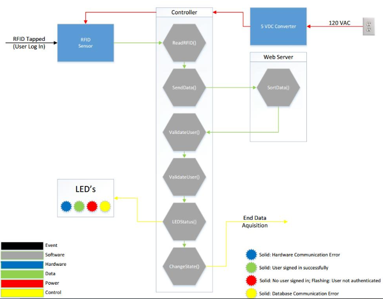
Figure 2 : User Entry Use Case.
The micro controller takes that data and searches the database for the user account. If the user is authenticated a green LED is lit. If the user is not authenticated the red LED will flash three times. If no connection was made to the database a yellow LED will light and remain lit until communication is restored. The micro controller will recheck for connection every 5 seconds until the connection is restored. At that point the system will reset and the red LED will once again light indicating the system is once again searching for log in. These steps are diagrammed in Figure 2.
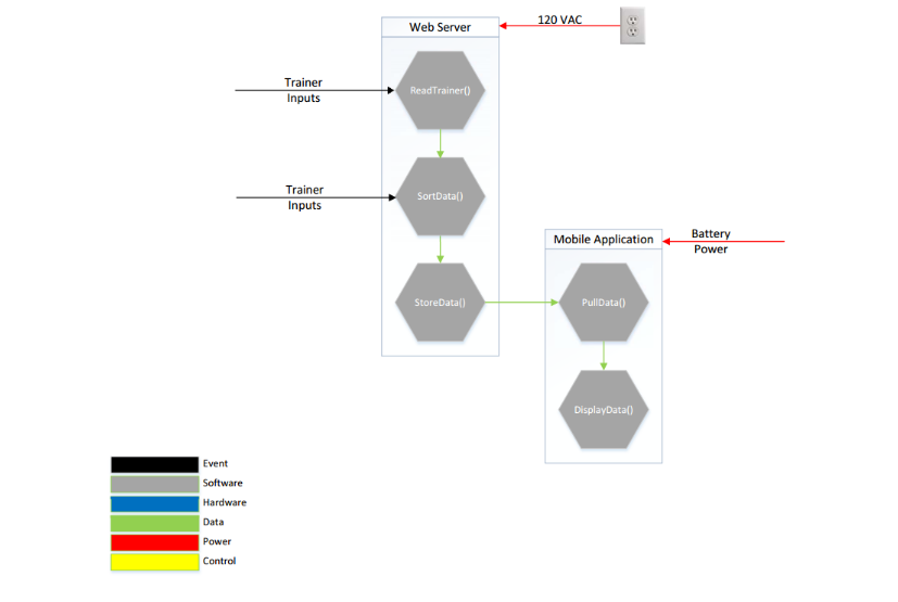
Figure 5 : Data Management Use Case.
The final use case describes how a user or trainer communicates with the system. If so chosen a third party such as a personal trainer can access the database and implement suggestions for weight and repetitions for each set of the exercise for a particular user on that day. This data will be available to the user through the smartphone application any time after this initial entry. Once a user performs their work out their weight and repetition data for each set will display adjacent to the suggested set data from the trainer.
Each set will be sent from the micro controller to the database and pulled to the smart phone when either the weight is at home position for 5 seconds or a user is signed out and sets will be displayed in chronological order. The third party will then have access to this data to evaluate performance and make future suggestions for the user. These steps are diagram in Figure 5.
ACCEPTED TECHNICAL DESIGN
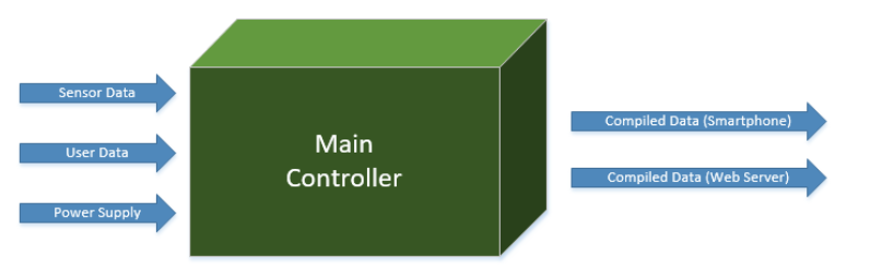
Figure 6 : Hardware Block Diagram (Level 0).
The main controller, shown in Figure 6, takes the incoming data from the system, compiles the data, and sends the compiled data to an outside server database. This data comes from the RFID, weight, infrared, and proximity sensors inputs. The information from the database is then read from a web server or a mobile phone application. The controller runs on 5 volts DC, and also distributes a reference voltage to the sensors.
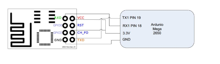
Figure 25 : Wi – Fi Chip hookup to Arduino.
The chip contains 8 pins GPIO_1, GPIO_2, Tx, Rx, 3.3V, Reset, Ground, and Chip Power down. For our purposes the GPIO and Reset pins will not be connected. The chip reset will be connected to the 3.3V supply. The connections are shown below in Figure 25.

Figure 30: Software Block Diagram (Level 2).
In the level 2 Software diagram the main function was further broken down to specific functions it may perform internally. These functions are the ValidateUser(), ProcessData(), and AddCounter(). Also the Webserver functions were grouped into a main function due to the fact that these functions may be performed in several different orders depending on what is being asked for. A function for trainer input was also added to this function. The mobile phone application was further broken down into the two main functions it will be performing, PullData() and DisplayData().
Source: The University of Akron
Author: Tyler M. Masters
>> Latest IoT Projects using Arduino for Engineering Students
>> 200+ IoT Led Projects for Final Year Students
>> IoT Software Projects for Final Year Students