ABSTRACT
Color measurements have traditionally been linked to expensive and difficult to handle equipment. The set of mathematical transformations that are needed to transfer a color that we observe in any object that doesn’t emit its own light (which is usually called a color-object) so that it can be displayed on a computer screen or printed on paper is not at all trivial. This usually requires a thorough knowledge of color spaces, colorimetric transformations and color management systems.
The TCS3414CS color sensor (I2C Sensor Color Grove), a system for capturing, processing and color management that allows the colors of any non-self-luminous object using a low-cost hardware based on Arduino, is presented in this paper. Specific software has been developed in Matlab and a study of the linearity of chromatic channels and accuracy of color measurements for this device has been undertaken. All used scripts (Arduino and Matlab) are attached as supplementary material. The results show acceptable accuracy values that, although obviously do not reach the levels obtained with the other scientific instruments, for the price difference they present a good low cost option.
COLOR SPACES
Device-independent Color Spaces
The first color space used as reference system universally accepted was XYZ tristimulus space, standardized by CIE in 1931. This space arises directly from the sensitivity of the three types of cones that are found in the human retina and various visual properties specified by mathematical laws known as the Grassmann’s laws and define it as Euclidean space.
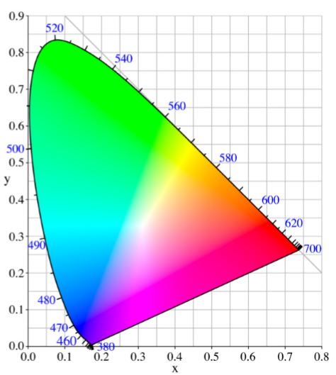
Since it was very difficult to represent a three-dimensional space graphically, a two dimension diagram is known as chromaticity diagram CIE 1931 xy (Figure 1) where chromaticity coordinates x,y are obtained by normalization x = X/(X + Y + Z); y = Y/(X + Y + Z) allowing dispensed with the third coordinate z since z = 1 − x − y. Furthermore, as in the definition of tristimulus space as the chromaticity diagram, took advantage to introduce certain boundary conditions which eliminate the possibility to appear negative coordinates and for illuminant equi-energy E had as chromaticity coordinates (x,y) = (0.33,0.33).

Figure 1. CIE 1931 chromaticity diagram
PROTOTYPE
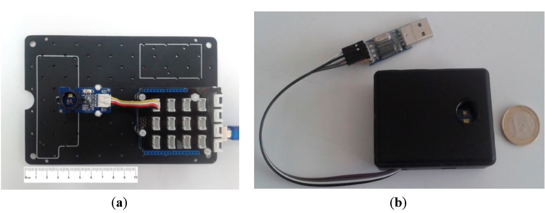
In order to build the prototype, we have used an Arduino Uno with a shield Grove—Base Shield V1.3 and a color sensor Grove—I2C Color Sensor (Figure 3a), the overall cost of the system is less than 70$. Arduino Uno is the basic board within the existing Arduino family, based on the ATmega328 chip. It has 14 digital input/output pins (of which six can be used as PWM outputs) and six analog inputs. The ATmega328 included also supports I2C and SPI communication. It contains everything needed to start developing your own prototype; simply connect it to a computer with a USB cable and program it. Besides, a new prototype based on an Arduino Mini for a higher portability with equal characteristics has been developed (Figure 3b).
EXPERIMENTAL PROCEDURE
Linearity in the Channels Response

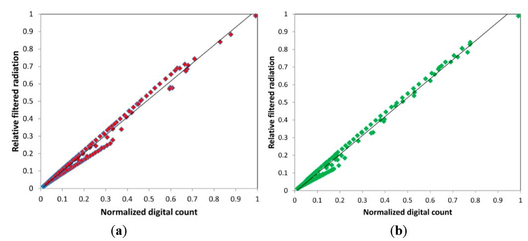
Figure 5. Normalized digital count VS. Relative filtered radiation received for the four channels (a) Red; (b) Green; (c) Blue; (d) Clear
This measuring instrument has a spectral measurement range between 380 and 780 nm and accuracy in the measurement of CIE 1931 xy chromaticity of x = 0.0015 y = 0.001. Using proprietary software developed in Visual Basic and automatic control of a light stimulation generator, the test device measurement and reference measurement device, we conducted a study of the linearity of the RGB channels of the color sensor as graphically displayed in Figure 5. In all the channels, the adjustment in the linearity obtained exceeds Pearson’s correlation coefficient of R > 0.99.
RESULTS AND DISCUSSION
Calibration
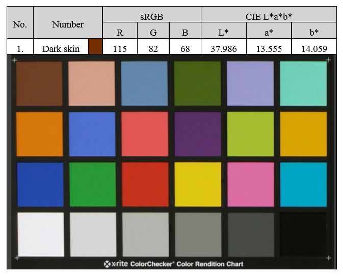
To simplify the calibration process used in preliminary experiments and adapted to the new objective of measuring solid colors, we have designed a calibration process based on the most widely recognized color card, the X-Rite Color Checker. This color card consists of 18 chromatic samples and 6 achromatic, and their chromaticities are provided by the manufacturer under the illuminant reference D65. Figure 7 shows a picture of the color chart with the values provided by the manufacturer for the first sample.

Figure 7. Chromatic chart ColorChecker and chromatic values in CIE Lab space and sRGB
CONCLUSIONS AND OUTLOOK
The possibilities that modular electronics offers are endless and, in a large part, this diversity is based on the existence of very different types of sensors, actuators, etc., their ease of use and low cost. In this case, the combination of Arduino, the Grove system and a color sensor accompanied by a high power white LED, can capture the color of any readily homogeneous solid object and display it on the screen of an electronic device in the most reliable way possible.
The results indicate that this system of color measurement has similar accuracy to other electronic devices, however without the accuracy of purely scientific instruments, but enough for a non-professional user. This shows that today valid research prototypes can perform for very low cost, although without the accuracy of commercial ones, providing an alternative for limited budgets.
In addition, as all the components are open hardware and the software is open source anyone can use and/or adapt the work presented in this paper following the philosophy of open knowledge. Moreover, this accuracy could be improved if a white light source LED that simulates the spectrum of the illuminant D65 is used as reference white in most colorimetric transformations.
Source: University Center of Merida
Authors: Juan Enrique Agudo | Pedro J. Pardo | Hector Sánchez | Angel Luis Pérez | Maria Isabel Suero
>> 50+ Matlab projects for Digital Image Processing for Final Year Students
>> More Matlab Projects using Arduino for Engineering Students
>> 80+ Matlab Projects based on Power Electronics for Engineering Students
>> More Analog Communication Projects using Matlab for Engineering Students
