ABSTRACT
Existing gas or electric water heaters can become inefficient through the overheating of water and through parasitic heat loss. These inefficiencies are able to be solved by monitoring when a home uses hot water. AquAdapt is a smart sensor which is capable of attaching to any existing residential gas or electric water heater.
By constantly monitoring the temperature change of a home water heater, the first law of thermodynamics can be used to relate temperature change to the amount of hot water leaving the water heater. Utilizing this information, a schedule can be generated to optimize the heating of home hot water. Regulating the on-off state of a water heater based on the household’s learned usage pattern, allows AquAdapt to reduce residential water heating energy consumption by up to 33%. With a final product cost of $60, the return on investment of AquAdapt is estimated to be 8 months.
SYSTEMS LEVEL
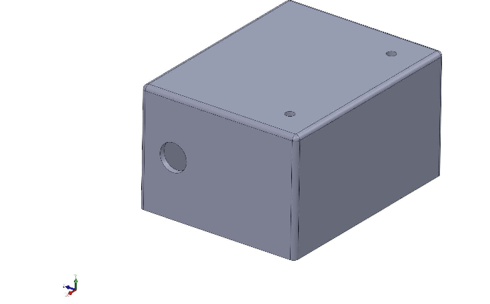
Figure 2.1: 3-D model of housing for PCB and thermocouples
The only required user interaction for the product is the installation. Following the given instructions, he or she will need to break the electrical connection with the water heater, and run the power into the controller first. The input power will be placed in the circular hole shown in the 3-D model in Figure 2.1. Afterwards the sensor needs to connect to the internet.
Once the controller has power, the customer will simply place the temperature sensor in the instructed location on the water heater. The temperature sensors will retract from the openings on top of the housing shown in Figure 2.1. Once the system is running and connected to the internet, there are no further requirements, and the system will begin the process of saving energy.
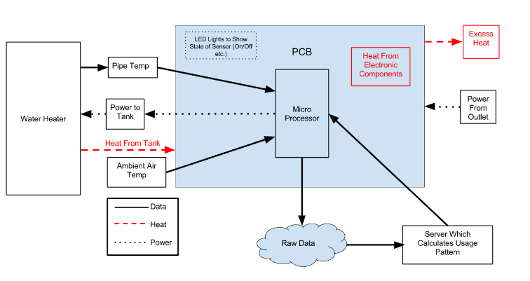
Figure 2.2: System layout of sensor, showing the inputs and outputs of the AquAdapt PCB
Figure 2.2 represents the general design of the system for an electric water heater. The arrows represent the inputs and outputs of the PCB data. After temperature inputs are collected and sent out by the microprocessor, a server analyzes the data and outputs a usage pattern, which the microprocessor receives and controls the power to the water tank. Also represented are the possible sources of heat that may be generated.
SUBSYSTEM 1: DATA COLLECTION, COMMUNICATION, AND CONTROL UNIT
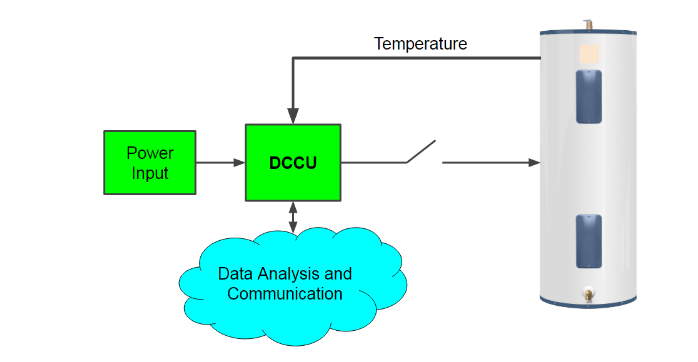
Figure 3.1: Diagram of the DCCU representing inputs (power, temperature, analysis results) and outputs (temperature data, heater control). Water heater represented on right.
Water heaters are typically kept in locations which are not often visited, such as a basement or a specific water heater closet. To collect data, send data, and control the water heater, our project’s DCCU utilizes a WiFi enabled microprocessor that can connect to a home’s wireless network. The processor takes input from two temperature sensors attached respectively to a hot water heater’s hot outlet and cold inlet pipes to monitor pipe temperature change, explained more in Chapter 5.
After sending the data through a home’s wireless network, an off-site server analyzes the data (further described in Chapter 4) and returns a schedule which the DCCU uses to control the gas or electric water heater. Figure 3.1 represents these inputs and outputs involved in the DCCU. All of these aspects described are compiled together in the form of a PCB allowing for compact and reliable usage. Additionally, in order to achieve our goal of having an affordable product, all individual parts in the DCCU are generic and not customized. The DCCU has a slightly different design depending on the type of water heater (gas or electric).
SUBSYSTEM 2: DATA ANALYSIS
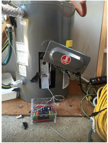
Figure 4.1: 10 Gallon Water Heater Experimental Set Up
In order to test the hypothesis that the conservation of energy equation could be used to find the mass flow rate of hot water leaving the tank, a 10 gallon water heater was utilized and connected to a traditional kitchen sink. This 10 gallon water heater had a temperature sensor attached to the inner tank’s surface. Using the changing temperature of the water heater, the mass flow rate can be calculated using curve fitting techniques. The experimental set up for the 10 gallon tank can be seen in Figure 4.1 below.
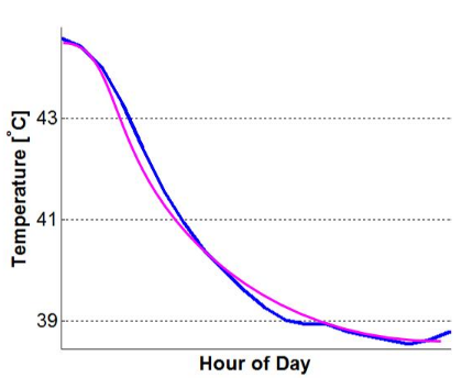
Figure 4.2: lsqcurvefit on Hot Water Draw
Blue is the collected data, smooth purple is the calculated data with lsqcurvefit. The better the fit, the better the approximation for the mass flow rate of hot water leaving the tank. In order to insure that the best fit for each data set is obtained, the temperature vs. time data is subjected to multiple iterations of lsqcurvefit over varying time ranges. An example of a good fit can be seen in figure 4.2.where the blue line is the temperature of the inner tank surface, and the pink line is the generated curve output from the MATLAB function lsqcurvefit.
SUBSYSTEM 3: HOUSING AND CLAMPS
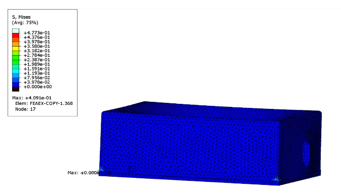
Figure 5.1: Deformation due to 3G force being applied to housings upper surface
To simulate a drop 3Gs of force was applied to the top of the housing. This was performed using Abacus and the results are shown below in Figure 5.1. From these results we could see that acrylic may not be the best material for the housing. We will have to use a stronger, less brittle material that will not break from a 1.52 m fall. However, using another material could potentially make it more difficult to manufacture the housing. We will take this into consideration for our final product.
COMPUTATIONAL ANALYSIS: INLET AND OUTLET PIPES
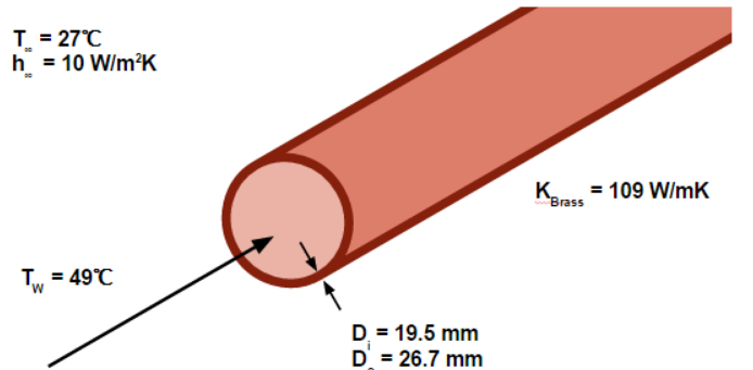
Figure 6.1: Sketch of Physical conditions of a hot outlet pipe
where TW is the temperature of the hot water, Di and Do are the inner and outer diameters of the pipe, respectively, K is the thermal conductivity, and h is the convective heat transfer coefficient.
SYSTEM INTEGRATION, TEST, AND RESULTS
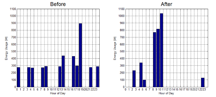
Figure 7.1: Energy Consumption by 10 Gallon Water Heater
The energy consumed by the 10 gallon water heater during the first week of operation can be seen on the left of the figure below, while on the graph on the right shows the energy consumption from the 10 gallon water heater with the AquAdapt sensor controlling the on and off state of the water heater.
It can be seen that the energy consumed by the water heater with the AquAdapt sensor installed leads to a reduction in energy being consumed. 33% less energy was consumed by the 10 gallon water heater with the AquAdapt sensor installed.
COSTING ANALYSIS
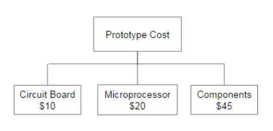
Figure 8.1: Prototype Cost Breakdown
In Figure 8.1 above, the prototype cost breakdown can be observed. The average cost to print a single 2 layered PCB is $10 for a single print. Our team will mostly be printing PCBs one at a time, in order to insure each PCB iteration can handle the desired requirements safely and effectively. The Photon microprocessor retails for $20 through the Particle website. As for the components that will go on the PCB, the estimated $45 stems from various components that will convert AC power to DC power to control the overall state of the water heater.
COST ANALYSIS
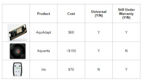
Table 9.1: Product comparison between AquAdapt, Aquanta, and Iris
The table 9.1 shown below shows a summary of the comparison between AquAdapt and the present competition on the market.
ENGINEERING STANDARDS AND REALISTIC CONSTRAINTS
Health and Safety
Safety was the most important issue in regards to our project. Large water heaters operate at high voltage and current levels, leading to the potential for shock to occur. The manufactured PCB needed to be able to transmit 240 volts at a current of 15 amps. To ensure that the manufactured PCB can handle this voltage, the initial design was presented to an ELEN professor which has experience in the field of PCB design.
- Environmental
- Economics
- Manufacturability
- Social Benefits
SUMMARY
The Aquadapt control system is a low cost, non-invasive device which reduces the amount of energy consumed by a typical household’s gas or electric water heater by up to 33%. Three subsystems will be implemented. First, temperature data will be collected and wirelessly sent to an off-site server for analysis. This server will parse through the data to create a usage pattern reflecting the amount of hot water that is required at a given hour of the day. This knowledge of required hot water needed will translate into times to turn on and off the water heater. Lastly, we made sure that the system was safely secured in a housing along with clamps that make installation simple for a typical homeowner.
The AquAdapt sensor has had the ability to demonstrate that current water heaters have the opportunity for energy savings. Further more the sensor has proven that the on off state of the water heater can be controlled for both gas and electric water heaters with an external controller. Finally AquAdapt has successfully demonstrated that a flow rate sensor is not necessary in order to calculate the mass flow rate of hot water leaving the tank. Further work includes creating a phone application which will allow the user to fully control their water heater remotely. Also creating a recognition code which will allow the sensor to recognize when different hot water appliances are being used.
Source: Santa Clara University
Authors: Joe Singer | Michael Simmons | Scott Jansen
>> 200+ Matlab Projects based on Control System for Final Year Students
>> More Matlab Engineering Projects based on Wireless Communication for Students
>> More Wireless Communication Projects in Matlab for Engineering Students
>> More Wireless Energy Projects for Final Year Students