ABSTRACT
The design of a wideband circularly polarized pixelated dielectric resonator antenna using a real-coded genetic algorithm (GA) is presented for far-field wireless power transfer applications. The antenna consists of a dielectric resonator (DR) which is discretized into 8 × 8 grid DR bars. The real-coded GA is utilized to estimate the optimal heights of the 64 DR bars to realize circular polarization.
The proposed antenna is excited by a narrow rectangular slot etched on the ground plane. A prototype of the proposed antenna is fabricated and tested. The measured −10 dB reflection and 3 dB axial ratio bandwidths are 32.32 % (2.62–3.63 GHz) and 14.63 % (2.85–3.30 GHz), respectively. A measured peak gain of 6.13 dBic is achieved at 3.2 GHz.
ANTENNA DESIGN
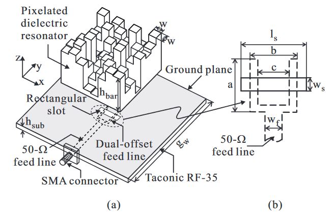
Figure 1. Geometry of the proposed antenna: (a) Exploded 3-D view; (b) Feeding configuration. SMA: SubMiniature version A
Figure 1a shows the geometry of the proposed DR and feeding structure. The antenna consists of a pixelated DR, a feeding line, a Taconic RF-35 dielectric substrate (with a thickness hsub = 1.52 mm, a relative dielectric constant of er = 3.5, and a loss tangent of tan δ = 0.0018), and a square ground plane. A rectangular slot with dimensions ws × ls = 3.6 mm × 21.4 mm is etched from the ground plane. The feeding line, consisting of a dual-offset feed line and a 50-Ω microstrip feed line, is mounted onto the bottom layer of the dielectric substrate (see Figure 1b).
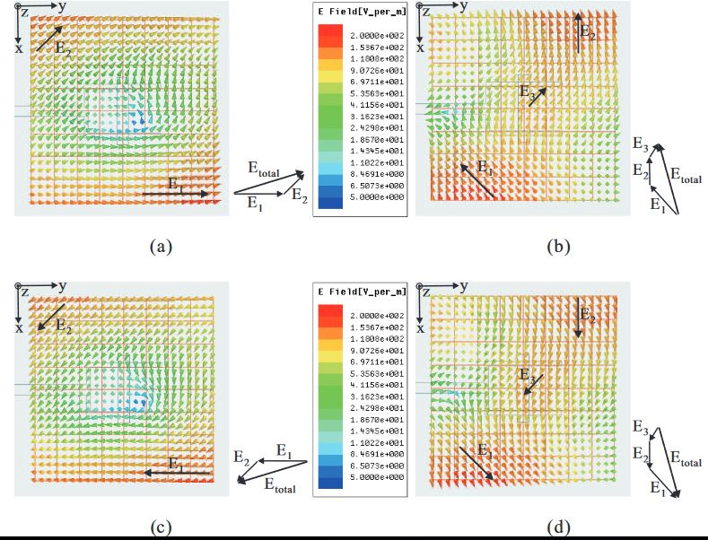
Figure 2. Simulated E-field distributions observed in the positive z -direction of the proposed dielectric resonator antenna (DRA) with time period T
In order to verify the generation of RHCP, the E-field distributions in the positive z-direction of the proposed DRA are investigated at a frequency of 3.1 GHz. Figure 2 shows the simulated E-field distributions observed on the observation plane, located at a height of 48.4 mm (corresponding to one half of free space wavelength at 3.1 GHz) from the ground plane. Note that E total is the vector sum of the major E-field components.
EXPERIMENTAL RESULTS AND DISCUSSION
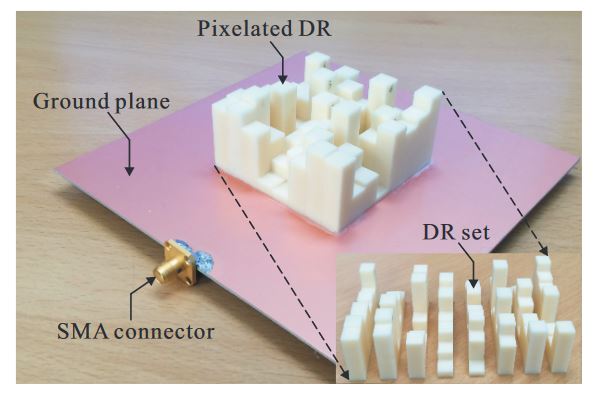
Figure 4. Photograph of the fabricated antenna
To simplify the milling process, the DR was divided into eight DR sets, with each DR set including eight DR bars along the y-axis. These fabricated DR sets were then glued together, after which their bottom sides were attached to the ground plane. A photograph of the fabricated antenna is shown in Figure 4. The reflection coefficient was measured using an Agilent 8510C network analyzer.
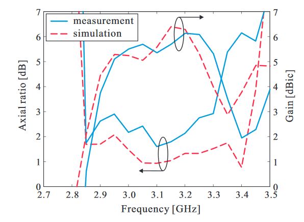
Figure 6. Measured and simulated axial ratios and right-handed circular polarization (RHCP) gains
Figure 6 shows the measured and simulated axial ratios (ARs) and RHCP gains of the proposed antenna along the broadside direction (θ = 0◦). The measured and simulated 3 dB AR bandwidths are 14.63 % (2.85–3.30 GHz) and 18.47 % (2.85–3.43 GHz), respectively. It was also noted that a measured peak RHCP gain of 6.13 dBic is achieved at 3.2 GHz.
CONCLUSIONS
A microstrip-fed wideband CP antenna with a pixelated DR was proposed, fabricated, and tested. The DR was discretized into 8 × 8 grid DR bars with different heights, with the heights optimized by a real-coded GA to realize circular polarization. The experimental results proved that the proposed antenna exhibits a wide −10 dB reflection bandwidth of 32.32 % (2.62–3.63 GHz), a 3 dB AR bandwidth of 14.63 % (2.85–3.30 GHz), and a peak gain of 6.13 dBic.
Compared to the LHCP gain, a high level of RHCP gain was also obtained in the broadside direction. Therefore, the proposed CP antenna, because it is capable of mitigating the polarization mismatch issue between the transmitter and receiver, is suitable for use as a wideband CP antenna element in far-field WPT applications.
Source: Sungkyunkwan University
Authors: Son Trinh-Van | Youngoo Yang | Kang-Yoon Lee | Keum Cheol Hwang
>> Project Report on Microstrip Patch Antenna for Final Year Students