ABSTRACT
This report describes the design, building, and testing of the Structure Climbing Monkey Robot (SCMR). It is composed of seven successive joints and linkages with two grippers at the two ends. Each gripper can act as the base or the end of the robot. The SCMR has the ability to climb any structure. The gripper plates can be changed to grab different kinds of structures, but this one is made to grab 2×4‘s.
A program was written to assist the user to grab four non-coplanar, non-orthogonal points. The SCMR is actuated by a total of nine motors: two to open and close the two grippers and seven to control the movement of the SCMR. Planetary gear motors are used with a worm gear to control the motion of each joint. The worm gear increases the torque of the motor and reduces the rotational speed to a usable value.
The SCMR is just over 45 inches long and weighs about 30 pounds. The motion of the SCMR is controlled by the microcontroller Arduino Mega 2560, Vex Robotic quadrature encoders, and Pololu 18v15 motor driver chips. Code was written in the languages Arduino and Processing to actuate the motors and create the GUI, respectively. The motors can be controlled individually or run simultaneously while incrementing a specified angle.
COMPUTER MODELING AND SIMULATION

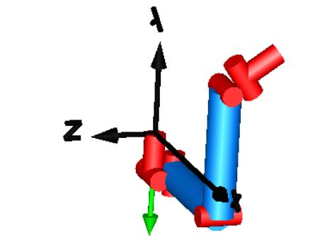
Figure 4 . Initial seven motor design in Dymola
With the failure of the six motor SCMR design, the testing of a seven motor SCMR began. Since one of the problems with the six motor SCMR design was that the gripper would be in the wrong orientation at the new gripping point, a motor must be attached to the gripper to rotate it. This was incoorperated into the successful design shown in Figure 4. This seven motor SCMR was able to reach any point and the gripper was able to rotate to any orientation for a secure grip of any structure.

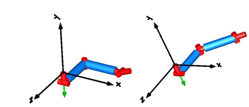
Figure 5. Alternative motor orientation designs of SCMR
The initial design of the SCMR had the axes of rotation of two of the motors in the “wrist” intersecting while the third axis of rotation was offset by a small distance. The adjustments were made to the SCMR while preserving the full mobility. This new design also allows the repositioning of the two motors closest to the “elbow” to either be at the “wrist” or at the “elbow” as seen in Figure 5.
BUILDING AND TESTING THE SCMR

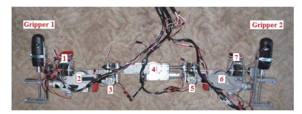
Figure 16. SCMR with motors numbered
From this point on, the numbering of the motors no longer skips four and six as it did for SimulationX. This was changed to be easier to understand for the code that controls the motion of the SCMR, described later. Figure 16 shows the numbering of the motors and grippers used.

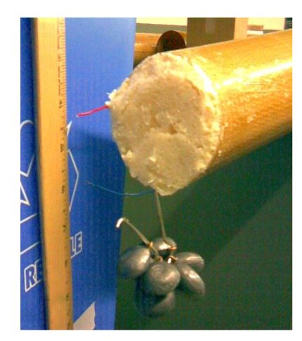
Figure 20. Third link test with foam-filled tube
For the third test, the tube was completely filled with foam (no cardboard inside) as shown in Figure 20. This still showed improvement in the deflection compared to the empty tube, but not as much as the second test. Much of the bending was done only at the clamped end where a section of the foam was cut out in order to affix the clamp.
DISCUSSION
Conclusion
Overall, the SCMR was successful. The SCMR was able to climb a structure by grabbing four non-coplanar points at non-orthogonal angles. The planetary gear motors with worm gears provided enough torque to power the SCMR through the critical positions of maximum load. The grippers are able to grab and release the structure using only commands from the computer. Releasing the gripper takes some practice to minimize the load on the gripper to be released.
Future Work
In order to improve the SCMR, there are a few more things that can be done to the hardware and software. As for the hardware, the SCMR can be made lighter and stronger. Holes can be drilled into the aluminum plates to make the SCMR lighter without making it weaker. More of the material can be milled away to create the same effect.
Source: California Polytechnic State University
Author: Paul Bessent