ABSTRACT
A vertical-strip-fed dielectric resonator antenna exhibiting broadband circular polarization characteristics is presented. A broad 3 dB axial ratio bandwidth (ARBW) is achieved by combining multiple orthogonal modes due to the use of a special-shaped dielectric resonator. The proposed antenna is fabricated to evaluate its actual performance capabilities. The antenna exhibits a measured 3 dB ARBW of 44.2% (3.35–5.25 GHz), lying within a−10 dB reflection bandwidth of 82.7% (2.44–5.88 GHz). The measured peak gain within 3 dB ARBW is found to be 5.66 dBic at 4.8 GHz. The measured results are in good agreement with the simulated results.
ANTENNA DESIGN
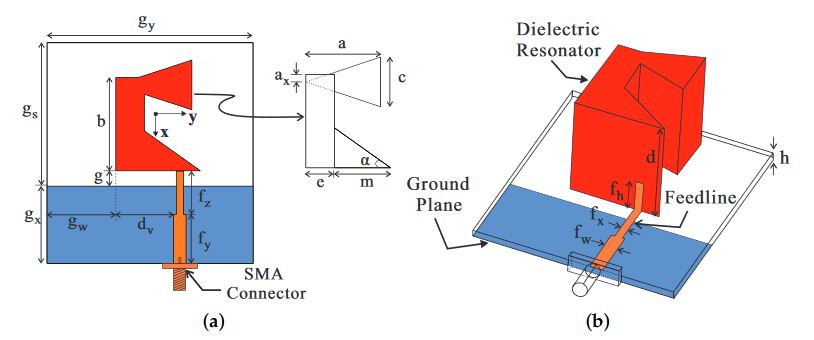
Figure 1. Geometry of the proposed antenna: (a) top view; (b) panoramic view. SMA: SubMiniature version A
Figure 1 shows the geometry of the proposed antenna. The DR has height d and consists of two triangular DRs and a rectangular DR made of a ceramic material with a relative dielectric constant εdr of 10 and tangent loss of 0.0002. A triangular DR with length m and angle α is connected to the lower side of the rectangular DR with length b and width e.
PARAMETRIC ANALYSIS
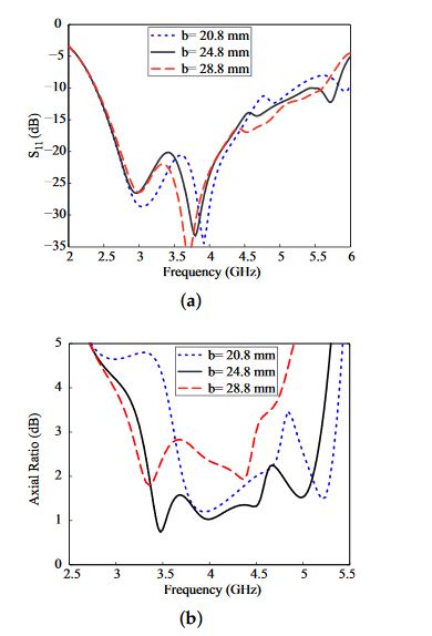
Figure 3. Effect of the variation of the dielectric resonator length b : (a) reflection coefficient; (b) axial ratio
The effect of the variation of DR length b on the −10 dB reflection bandwidth and the 3 dB ARBW is shown in Figure 3. It was noted that the variation in length b was towards the negative x-axis with no effect on distance g. Figure 3a shows that the −10 dB reflection bandwidth remained mostly unaffected by these variations. On the other hand, the 3 dB ARBW moved towards lower frequencies with an increase in b, as shown in figure 3b.
MEASUREMENT RESULTS AND DISCUSSION
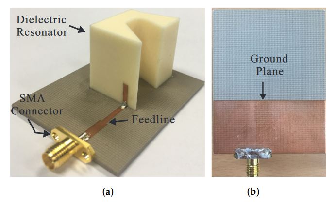
Figure 6. Photograph of the proposed antenna: (a) panoramic view; (b) bottom view
Figure 6 shows a photograph of the fabricated antenna using the optimum parameters listed in Table 1. The reflection coefficient was measured using an Agilent 8510C network analyzer and the comparison with the simulated result is presented in Figure 7. The simulated and measured −10 dB reflection bandwidths were 82.9% (2.4–5.8 GHz) and 82.7% (2.44–5.88 GHz), respectively. The far-field measurement was conducted in an RF anechoic chamber, which utilizes a dual-polarized horn antenna to assess the AR and right-handed circular polarization (RHCP)/LHCP radiation.
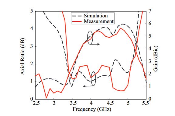
Figure 8. Simulated and measured axial ratios and left-handed circular polarization (LHCP) gains of the proposed antenna
The far-field measurement was conducted in an RF anechoic chamber, which utilizes a dual-polarized horn antenna to assess the AR and right-handed circular polarization (RHCP)/LHCP radiation. The comparison of the simulated and measured 3 dB ARs and LHCP gains—in the broadside direction (θ = 0◦)—is depicted in Figure 8.
CONCLUSIONS
A simple broadband CP DRA with vertical-strip excitation is presented. The antenna is designed with a partial ground plane. A fair performance comparison between the proposed and rectangular DRs is carried out. It is concluded that the proposed DR, due to its shape, combines multiple orthogonal modes to produce a broad 3 dB ARBW. The proposed antenna is evaluated after fabrication, achieving a measured−10 dB reflection bandwidth of 82.7% (2.44–5.88 GHz).
The measured 3 dB ARBW of 44.2% (3.35–5.25 GHz) with a peak LHCP gain of 5.66 dBic lies within the−10 dB reflection bandwidth. Good agreement is found between the simulated and measured results. Radiation patterns were noted at different frequencies. On both planes, the purity of the measured LHCP gain is greater than 16 dB from RHCP in the broadside direction. In short, due to its broad 3 dB ARBW performance and simple feeding technique, the proposed antenna is a potential candidate for various CP applications.
Source: Dongguk University
Authors: Amir Altaf | Jin-Woo Jung | Youngoo Yang | Kang-Yoon Lee | Keum Cheol Hwang