ABSTRACT
This paper presents the design of a wideband circularly polarized antenna using a multiple-circular-sector dielectric resonator (DR). The DR is composed of twelve circular-sector DRs with identical central angles of 30◦ but with different radii. A genetic algorithm is utilized to optimize the radii of the twelve circular-sector DRs to realize wideband circular polarization. The proposed antenna is excited using an aperture-coupled feeding technique through a narrow rectangular slot etched onto the ground plane.
An antenna prototype is experimentally verified. The measured −10 dB reflection and 3 dB axial ratio (AR) bandwidths are 31.39 % (1.88–2.58 GHz) and 19.30 % (2.06–2.50 GHz), respectively, covering the operating bands of the following systems: UMTS-2100 (2.145 GHz), WiMAX (2.3 GHz), and Wi-Fi (2.445 GHz). A measured peak gain of 7.65 dBic at 2.225 GHz and gain variation of less than 2.70 dBic within the measured 3 dB AR bandwidth are achieved. In addition, the radiation patterns of the proposed antenna are presented and discussed.
ANTENNA DESIGN
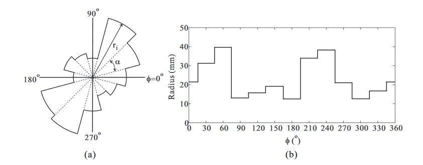
Figure 1. Multiple-circular-sector structure: (a) Shape of the multiple-circular-sector; (b) Radii at different angles
Figure 1 illustrates the concept of the multiple-circular-sector structure. The multiple-circular-sector structure was previously introduced in earlier works. It was initially proposed by Yeung et al. for the design of an ultra-wideband patch antenna. In a subsequent work, Yeung et al successfully implemented a wideband circularly polarized multiple-circular-sector slot antenna.
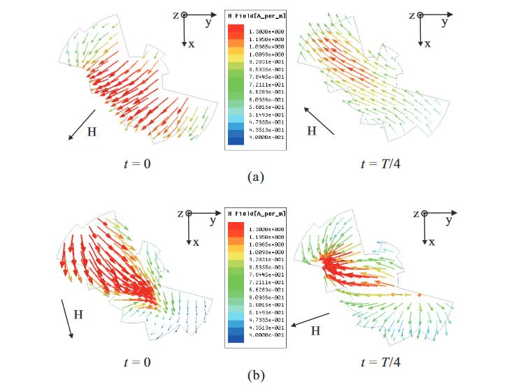
Figure 3. Simulated H-field distributions on the top surface of the proposed multiple-circular-sector dielectric resonator (DR) with time period
In order to verify the generation of LHCP, the H-field distribution on the top surface of the proposed multiple-circular-sector DR is investigated. Figure 3a presents the simulated H-field distribution observed in the positive z-direction at a frequency of 2.3 GHz. When t = 0, the vector of the major H-field distributions points from the upper right corner to the lower left corner.
EXPERIMENTAL RESULTS AND DISCUSSION
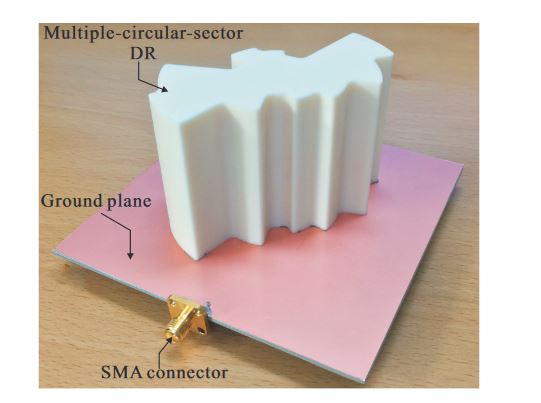
Figure 7. Photograph of the fabricated antenna
Based on the optimized design parameters listed in Table 1, a prototype of the proposed antenna was fabricated. A 99.5 % alumina ceramic material with a dielectric constant of 9.8 and a loss tangent of 0.0001 was utilized to fabricate the proposed DR. Figure 7 shows a photograph of the fabricated antenna. Epoxy adhesive was used to glue the bottom layer of the multiple-circular-sector DR to the ground plane.

Figure 8. Measured and simulated reflection coefficients
An Agilent 8510C network analyzer was used to measure the reflection coefficient of the fabricated antenna. The measured and simulated results of the reflection coefficients are illustrated in Figure 8. Good agreement between the measurement and simulation results was achieved. It was found that the measured and simulated −10 dB reflection bandwidths were 31.39 % (1.88–2.58 GHz) and 29.33% (1.91–2.58 GHz), respectively.
CONCLUSIONS
The design of a microstrip-fed wideband CP antenna using a multiple-circular-sector DR was proposed, fabricated, and measured. The DR was composed of twelve circular-sector DRs, all with identical central angles of 30◦, but with different radii. The radii were optimized using a GA to realize wideband CP operation. The experimental results proved that the proposed antenna has a wide −10 dB reflection bandwidth of 31.39 % (1.88–2.58 GHz), a wide 3 dB AR bandwidth of 19.30 % (2.06–2.50 GHz), a peak gain of 7.65 dBic, and a high level of LHCP gain compared to the RHCP gain in the broadside direction.
The CP operation frequency range of the proposed antenna covers the operating bands of several systems, such as UMTS-2100 (2.145 GHz), WiMAX (2.3 GHz), and Wi-Fi (2.445 GHz). Therefore, the proposed antenna is feasible for use as a wideband CP antenna element for wireless communication applications and satellite communication systems.
Source: Sungkyunkwan University
Authors: Son Trinh-Van | Youngoo Yang | Kang-Yoon Lee | Keum Cheol Hwang
>> 60+ Antenna Communication Projects for Engineering Students
>> Antenna Based Projects List for Engineering Students
>> Antenna Design Projects for Final Year Students
>> More Wireless Hacking Projects for Wi-fi Enthusiasts for Engineering Students