ABSTRACT
The goal of our project is to create a software architecture that makes it possible to easily control a multi- robot system, as well as seamlessly change control modes during operation. The different control schemes first include the ability to implement on-board and off-board controllers. Second, the commands can specify either actuator level, vehicle level, or fleet level behavior.
Finally, motion can be specified by giving a way-point and time constraint, a velocity and heading, or a throttle and angle.Our code is abstracted so that any type of robot – ranging from ones that use a differential drive set up, to three-wheeled holonomic platforms, to quadcopters – can be added to the system by simply writing drivers that interface with the hardware used and by implementing math packages that do the required calculations.
Our team has successfully demonstrated piloting a single robots while switching between way point navigation and a joystick controller. In addition, we have demonstrated the synchronized control of two robots using joystick control. Future work includes implementing a more robust cluster control, including off -board functionality, and incorporating our architecture into different types of robots.
SYSTEM OVERVIEW
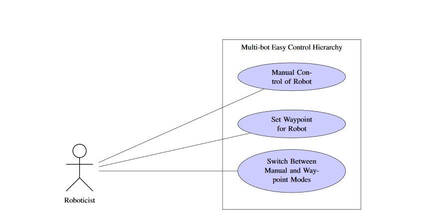
Figure 2.1: Use Case for Multi-bot Easy Control Hierarchy.
Figure 2.1 shows the use cases that define the tasks that a user can perform to achieve a certain goal within our system. The use cases have two primary components: a detailed description of each use case and a summary diagram. The use case descriptions include the preconditions and post conditions needed to achieve a certain goal, the type of user involved, what steps the user needs to perform to reach the use case goal, as well as exceptions that the system may encounter.
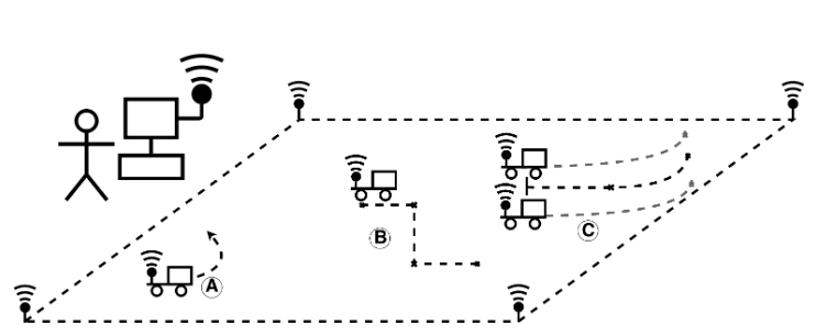
Figure 2.2: Physical Depiction
Figure 2.2 shows the different methods of control in our system. Navigation mode A is manual drive with joystick control. Mode B is way point navigation by specifying points through the user interface. Mode C is way point navigation with cluster control. The user, depicted by the stick figure, has configured MECH and is monitoring its operation. The computer has the ground control version of MECH that allows for the user to configure the robots with a GUI.

Figure 2.5: Architecture Diagram for Robot Software.
Figure 2.5 depicts the high level software architecture that handles the data flow of MECH on the robot. The robot runs a Linux operating system that has Python 2.7 and Java 8 installed. A Java process handles the communication with Data turbine and reconfiguration of which controller the robot is listening to when the UI requests the robot to reconfigure.
Java also communicates with the Python code via a unix domain socket. Python handles all of the data parsing and control of the hardware. Each ellipse in Figure 2.5 represents a python process that runs on the robot. The python process are started by DDStarter.py. DDStarter.py and the Java process on the robot are started with StartRobot.sh
USER INTERFACE
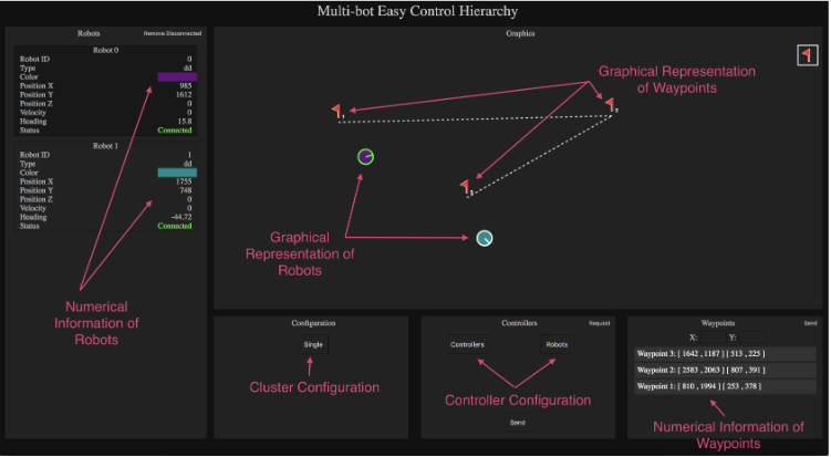
Figure 3.3: Overview of the User Interface.
The design later was updated as the architecture evolved to utilize Dataturbine to automatically add robots to the system. After the controllers and waypoint navigation were added to the architecture, the design changed yet again, into its final version as shown in Figure 3.3.
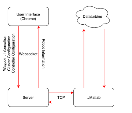
Figure 3.12: Data Flow Diagram of the User Interface.
The back end of the user interface consists of a server written in Node.js. Node.js is the perfect programming language for such a server, as it allows for bidirectional and asynchronous flow of information. The purpose of the back-end server is to relay information between the website and JMatlab. The server communicates with the website through a websocket. A websocket library called ”ws” was used. The connection to JMatlab is through TCP, which is natively supported by Node.js, so no external libraries were utilized. The information forwarding and flow is shown in Figure 3.12.
ROBOT PROTOTYPE
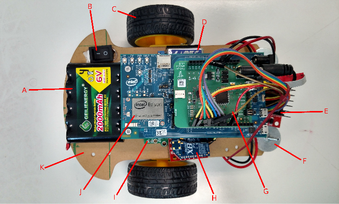
Figure 4.1: Robot Prototype
We designed the robot that we used to test our software. Most of the components on the robot are depicted in Figure 4.1. The components were a 6V 2000mAh NiMH battery(A), power switch(B), two pow- ered wheels(C), a 5V 3A UBEC voltage regulator(D), a L298 dual H-bridge motor controller(E), 8 washers for counterweight(F), Pozyx position tag(G), XBee communication module(H), optical motor encoders(I), a microprocessor, in this case an Intel Edison with Arduino breakout board(J), and an acrylic chassis(K). The components missing from Figure 4.1 are a caster wheel, and a 6V to 9V boost converter.
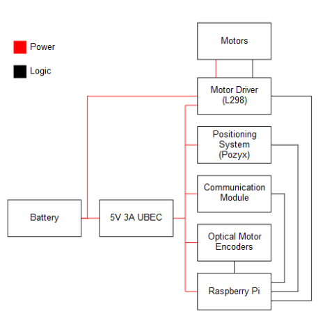
Figure 4.3: Raspberry Pi Component Block Diagram
The XBee module and optical motor encoders were unused and removed from the scope of the project, as we determined they were not critical components for the success of our project and our time was better spent tackling other problems. Instead of communicating via the XBee, we used the built-in WiFi that came on the Raspberry Pi and the Intel Edison. The XBee would have been our proof that the software supports different communication hardware and protocols.
SWITCHING ARCHITECTURE
Design
One of the main features of our architecture is the ability to seamlessly switch the controller of a robot, or a cluster, to another. Even though the switching architecture is extensive and involves code in three different layers – Matlab, jMatlab, and the user interface – the user of the system is easily able to use this functionality through the GUI. With the push of a button, the website updates the list of available controllers and robots in the system, and populates two drop down menus. The list can be refreshed any time by performing the same actions.
POZYX
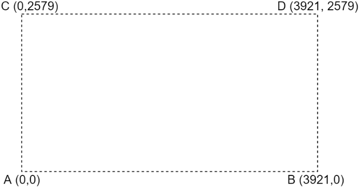
Figure 6.3: Pozyx Anchor Layout.
The Pozyx anchor position is shown in Figure 6.3. Since these changes can affect accuracy of marked waypoints through days of repeated testing and that we are sharing these anchors with other groups who are testing with different height specifications, we decided to put all the anchors on the ground because it easier to setup because it requires zero to minimal amount of remeasurements for height.
SOCIETAL ISSUES
Our team created a control architecture to aid engineers in the operation and creation of robots. The project spans interdisciplinary studies from computer engineering to electrical and mechanical engineering. Because of this, the ethical components of our architecture will include the components from the electrical and mechanical engineering field. We must consider the ethics behind robots and their interactions with humans, the environment, and other robots. Multi-bot Easy Control Hierarchy (MECH) aims to alleviate the problems that engineers face when using and creating a robot.
Summary
Our team’s objective was to make an architecture that makes it easy to seamlessly switch between controllers and various types of control signals such as actuator, velocity, and fleet levels. Extra precaution had to be taken during the reconfiguration of our system as the different controllers need to be synchronized and the communication between controllers and robots needs to be correctly routed. Our team developed an architecture that fforded roboticists the ability to change the configuration of their robots’ controller.
The user can configure and monitor their robots through a web-based graphical user interface (GUI). Various changes can be made to the Matlab controllers, Python algorithms, and Simulink blocks to obtain the desired setup. The Pozyx indoors positioning system tracks the location of the robot and allows the user to employ waypoint navigation if needed. We have successfully demonstrated controlling two differential-drive robots individually and simultaneously with either waypoint navigation or joystick controller while also being able to switch between these two forms of control through the graphical user interface.
FUTURE WORK
Due to time limitations, we were unable to implement off -board waypoint calculations in Matlab. There were also plans to implement more advanced forms of cluster control, such as follow-the-leader and various pattern formations. In the future, we hope to implement additional key features into our architecture, as well as run tests that incorporate a more extensive set of hardware in order to ensure cross-platform compatibility. Our immediate attention is focused on adding off-board calculations in Matlab and later creating more complex cluster control algorithms. A good starting point to ensure cross-platform compatibility would be to incorporate GPS and XBee technology into newly built robots utilizing our architecture.
Source: Santa Clara University
Authors: Ryan Cooper | Marton Demeter | Jonathan Ho | Alan Nguyen
>> Latest IoT Projects using Raspberry Pi for Engineering Students
>> Latest IoT based Robotics Projects for Engineering Students
>> Top IoT Projects using Matlab for B.E/B.Tech Students
>> 200+ IoT Led Projects for Final Year Students
>> IoT Software Projects for Final Year Students
>> More Matlab Projects using Arduino for Final Year Students
>> 200+ Matlab Projects based on Control System for Final Year Students
>> Simple Java Projects with Source Code Free Download and Documentation