ABSTRACT
The DC servo motor has applications in automotive market in applications ranging from heating and ventilation to power mirror positioning. It is also in use in Industrial and Consumer Markets for entertainment equipment, HVAC ventilation control and myriad number of other applications.
In all these applications, either speed or position control of the DC servo motor is used.
In this project, we have achieved MATLAB based real – time speed control implementation of DC servo motor using PCI – 1716.
For a more efficient speed control, closed loop control system of the servo motor is realized with the help of a tuned PID controller.
Further, progress has also been made in remote control of DC servo motor. For this, a communication has been established between the local and the r emote PC; and PID controlled closed loop system, with the controller at the remote PC was successfully achieved and checked for optimal performance.
However, due to delays introduced in the communication system, the remote control using PID was not found to be as efficient as the local control and the speed output was found to lag behind the reference signal. To compensate for this delay, a Smith Predictor incorporated model has been made.
DATA ACQUISITION THROUGH THE PCI CARD (PCI 1716)
PCI-1716 and PCI-1716L are powerful high-resolution multifunction cards for the PCI bus. They feature a 250 kS/s 16-bit A/D converter, and an onboard 1,024-sample FIFO buffer for A/D. The cards have up to 16 single-ended or 8 differential A/D input channels or a combination of these; two 16-bit D/A output channels, 16 digital input/output channels, and one 10 MHz 16-bit counter channel. PCI-1716 and PCI-1716L provide specific functions for different user requirements.
LOCAL SPEED CONTROL OF DC SERVO MOTOR
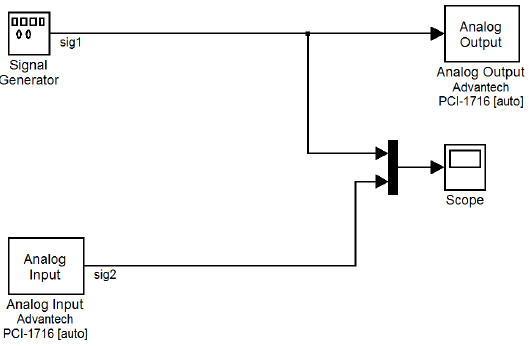
Fig 3.1: Simulink model for running the motor in open loop
Open loop configuration is suited for systems where the relationship between the input and the resultant state can be modeled by a mathematical formula, and the load is predefined and fixed. For example, for a motor driving a constant load, the desired speed can be easily obtained in open loop by appropriately changing the input voltage. But, if the load were unpredictable, the motor-speed would be a function of the input voltage as well as the load. In such a case, open loop control would not give satisfactory results.
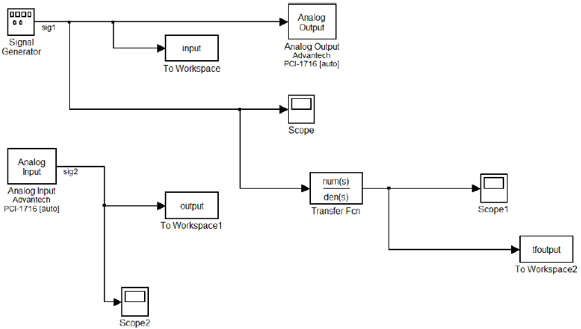
Fig 3.13: Simulink model for comparison of open-loop response of the transfer function and that of the motor
The Simulink block diagram for comparison of open-loop response of the transfer function and that of the motor is shown on the next page. The analog input and output blocks are se with values as shown previously. And the transfer function block Is set with the transfer function obtained in the previous sub-section.
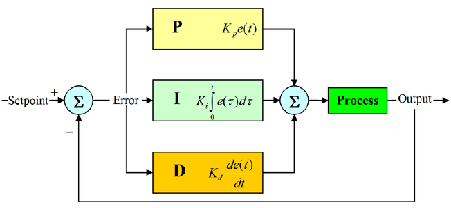
Fig 3.16: PID controller in closed loop
A proportional–integral–derivative controller (PID controller) is a controller which is popularly used in industrial control systems . It is fed with the error signal, that is, the difference between the reference, or the desired output and the actual output (which is obtained as a feedback). The controller then attempts to bring the actual output to track the reference.

Fig 3.22: PID Control Model of real system
The closed loop control system for the motor using a PID controller is modeled as the Simulink model shown below. Here, the analog input and output blocks are set as shown previously. The saturation block is used to limit the PID output to certain prefixed values.
WHAT IS UDP?
UDP uses a simple transmission model without implicit handshaking dialogues for providing reliability, ordering, or data integrity. Thus, UDP provides an unreliable service and datagrams may arrive out of order, appear duplicated, or go missing without notice. UDP assumes that error checking and correction is either not necessary or performed in the application, avoiding the overhead of such processing at the network interface level. Time-sensitive applications often use UDP because dropping packets is preferable to waiting for delayed packets, which may not be an option in a real-time system.
SET UP OF UDP COMMUNICATION BETWEEN TWO COMPUTERS USING MATLAB
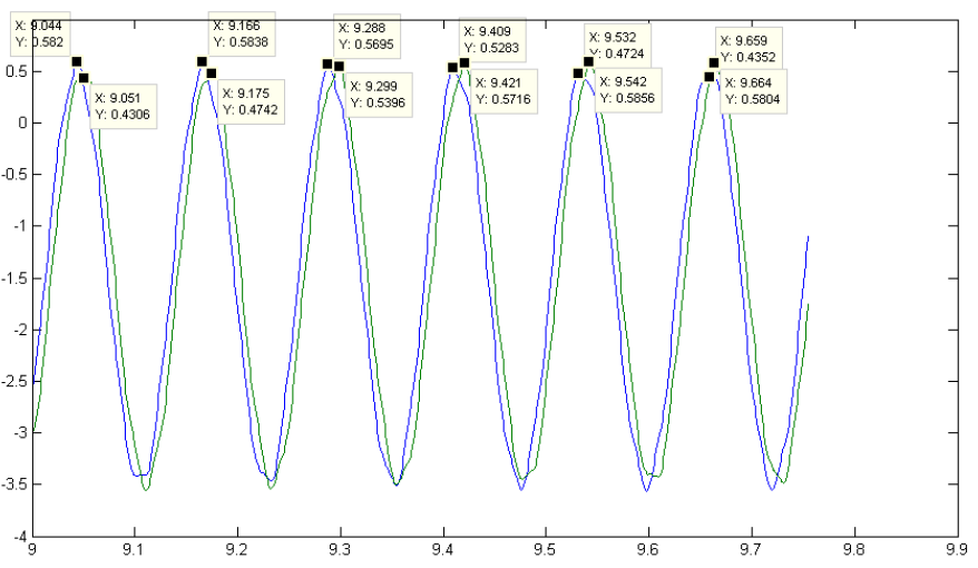
Fig 5.10: Network Delay Graph
This will enable us to set up communication between two PCs. When the models are run the remote PC is able to receive the signal sent with some delay. A closed loop was formed and it was found that the data sent to and fro took 0.009 seconds to complete the loop. The network characteristic is shown.
REMOTE CONTROL OF DC SERVO MOTOR USING PID CONTROLLER
Simulink Model for Local PC
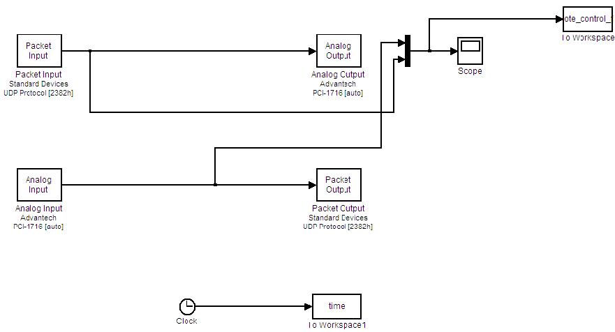
Fig 6.1: Simulink Model Local PC
Blocks used –
I. Packet IP/OP
II. Analog IP/OP
III. Scope (to compare the input signal with the speed output)
Here Packet IP/OP blocks are used to receive the control signal and send the speed output. Analog IP and Analog OP are the interfacing blocks for PCI card.
Simulink Model for Remote PC
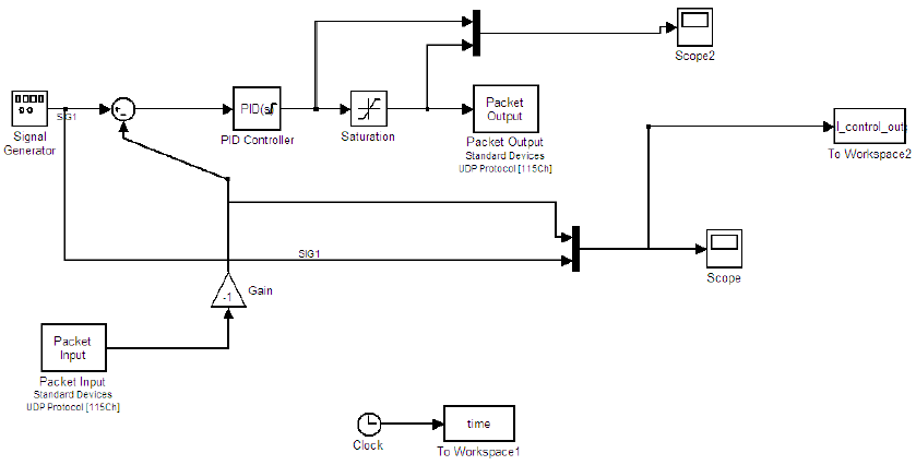
Fig 6.2: Simulink Model Remote PC
Blocks used –
I. Packet IP/OP
II. Analog IP/OP
III. PID
IV. Saturation (used to limit the PID gain)
V. Sum
VI. Gain
REMOTE CONTROL BY USE OF SMITH PREDICTOR
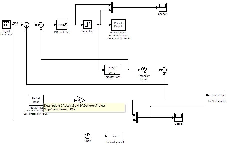
Fig 7.1: Smith Predictor Simulink Model
The transfer function used was derived earlier for design of PID controller. The transport delay could not be measured correctly and so the desired result was not obtained.
CONCLUSION AND SCOPE FOR FUTURE WORK
Conclusion
This thesis presents study on MATLAB (2010 version) based real-time control implementation of the DC servo motor using PCI-1716.
It was observed that on running the motor in open loop, the speed output does not successfully track the reference. So, the need for a closed loop control system was realized.
To achieve this, the system was modeled using System Identification Toolbox of MATLAB, and a PID controller was designed for the model. Then the system was run in closed loop configuration. It was observed that the speed output of the closed loop control system successfully tracks the reference.
Then, to achieve remote control of the DC servo motor through PCI card, using MATLAB, a communication was set up between two computers based on UDP. The total time delay in sending a signal from one PC to another and receiving the same signal back was also calculated.
Finally, the motor speed was controlled from a remote computer using PID controller. It was observed that the communication network introduced delay in the system output with respect to the reference. These delays may have an effect on the stability and performance of the system.
Scope for Future Work
To compensate for the communication delay during remote control of the motor, Smith predictor may be used. The Simulink model for the same has been given in the thesis. However, we have not been able to obtain satisfactory results using Smith Predictor. The necessary modifications may be made to the model (using Smith Predictor) for a more efficient remote control of the DC servo motor.
Source: National Institute of Technology
Authors: Ananya Roy | Aditya Gazta | Suneet Sahadevan
>> Simple Matlab Projects for EEE Final Year Students
>> Easy Microcontroller Project Ideas for Students
>> 50+ Matlab projects for Digital Image Processing for Engineering Students
>> More Matlab Projects on Signals and Systems for Engineering Students
>> 200+ Matlab Projects based on Control System for Final Year Students
>> More Analog Communication Projects using Matlab for Final Year Students