ABSTRACT
With the development of the highway transportation and business trade, vehicle Weigh-In-Motion (WIM) technology has become a key technology for measuring traffic loads. In this paper a novel WIM system base d on monitoring of pavement strain responses in rigid pavement was investigated. In this WIM system multiple low cost, light weight, small volume and high accuracy embedded concrete strain sensors were used as WIM sensors to measure rigid pavement strain responses.
In order to verify the feasibility of the method, a system prototype based on multiple sensors was designed and deployed on a relatively busy freeway. Field calibration and tests were performed with known two-axle truck wheel loads and the measurement errors were calculated based on the static weights measured with a static weighbridge. This enables the weights of other vehicles to be calculated from the calibration constant.
Calibration and test results for individual sensors or three-sensor fusions are both provided. Repeatability, sources of error, and weight accuracy are discussed. Successful results showed that the proposed method was feasible and proven to have a high accuracy. Furthermore, a sample mean approach using multiple fused individual sensors could provide better performance compared to individual sensors.
DESCRIPTION OF THE METHODOLOGY
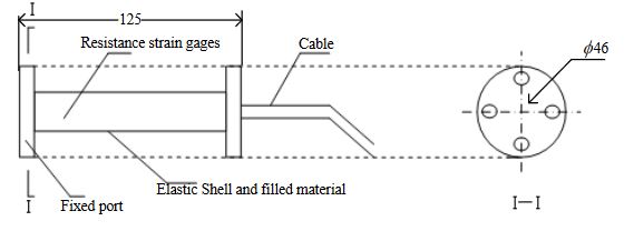
Figure 2. Structural sketch of the strain sensor (Units: mm)
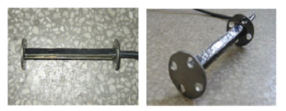
Figure 3. Photos of the strain sensor
Figures 2 and 3 show the structural sketch of the embedded concrete dynamic strain sensor and the photos, respectively. The embedment strain sensors are designed for direct embedment in concrete pavement. The dimension of the strip strain sensors is 12.5 cm gauge length, 1.2 cm width and 1 cm thickness.
DESCRIPTION OF FIELD TEST BENCH
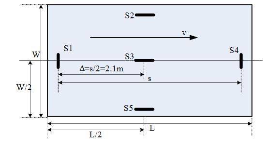
Figure 6. Deployment of proposed WIM system on a lane freeway
Five embedded concrete strain sensors are deployed at the bottom of the pavement slab of a lane on freeway to measure the strain response of the pavement rather than to measure the forces of the axle load on the sensors as in current WIM stations (see Figure 6). S1, S3 and S4 are used as primary sensors to measure axle load, S2, S5 are used as adjunct sensors to determine relative location of wheel loads and monitor pavement structure.
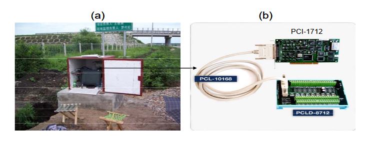
Figure 9. (a) Photo of the data collection device; (b) Data collection card and interface board
The data acquisition system (see Figure 9b) is connected to the junction box of each section to record the dynamic pavement response resulting from a moving wheel load. The acquisition program, written in C++, provided for different sampling rates and times. A sampling rate of 2 kHz for 2 sec for each channel was found to be most appropriate for this installation.
EXPERIMENTAL RESULTS AND ANALYSIS
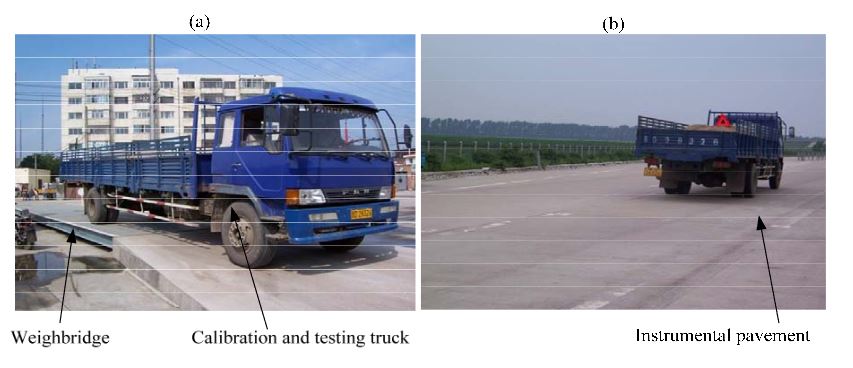
Figure 13. A two-axle truck for calibration and testing (a) vehicle static wheel load on a static whole-vehicle weighbridge; (b) vehicle passing the instrumental pavement
A two-axle truck was used for calibration and testing on the proposed WIM system (refer to Figure 13). The vehicle was arranged into a tandem axle combination. The combination was coded A1 and A2 and static axle weight was described in Table 1. The vehicle combination was selected to be relatively representative of a typical Chinese truck.
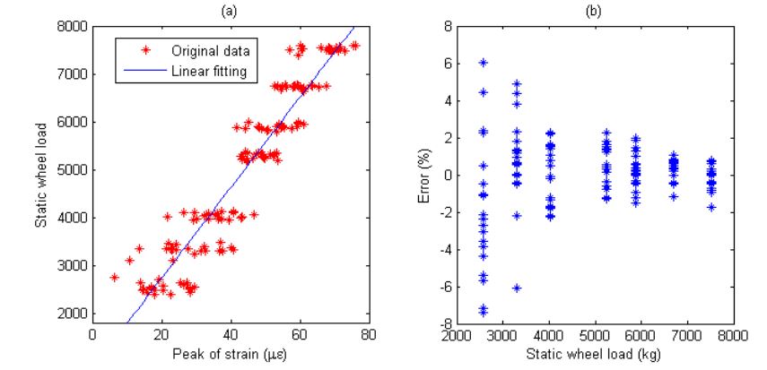
Figure 19. (a) Weight calibration function (y=94.4x+843.7) for S4 on trailer axle. (b) Error of axle weight measurement for S4 on Trailer axle
Short-term repeatability of results are show in calibration curve (refer to Figures 14a-19a). Sensor data points at similar speeds, wheel loads and passing location were acquired at times of up to 1 hour or more part, each run taking some 2 hr in all. The standard deviation of the strain difference of data points from the curve of linear fit to the data in this case was 3.3% of the maximum ordinate.
CONCLUSIONS
In a WIM system, the gross weight or the axle weight of the passing vehicle can be measured dynamically by the sensors installed in or on the pavement. Traditional measurement method just uses the interactions between the sensor and the vehicle’s tires that make the measurement inaccurate because the sensor cannot cover the whole tire patch along the driving direction. A novel WIM method based on pavement strain response is proposed in this paper.
Since the pavement strain is caused by an entire moving vehicular wheel load; it covers a longer force duration time than current WIM methods, so higher measurement accuracy is expected by considering the pavement strain. The proposed method has more durability, lower system maintenance costs (due to its embedded installation), good concealment (improved road safety), little environmental impact (uninterrupted continuous measurement), low cost for individual sensors (providing the possibility of using multiple sensors in a WIM system).
A major contribution of this paper was to design, build, and test of a novel experimental WIM system prototype based on a radically different approach than current WIM systems. The field tests and calibration experiments were presented. The results verified that using the embedded strain sensors was feasible and multiple sensors fusion could get higher accuracy and confidence level than individual sensor. In the paper, only experiments at the same nominal speed have been researched and analyzed and the accuracy of WIM measured vehicle weights has not been affected obviously by speed.
In the future, experiments under high speed conditions could be performed and the effect of speed studied. Other features such as temperature properties of the sensor and installation issues are to be studied too. Furthermore, only the sample mean multiple fusion method has been research and tested in this paper, so in order to achieve the higher precision more algorithms are to be applied to the MS-WIM.
Authors: Wenbin Zhang | Chunguang Suo | Qi Wang