ABSTRACT
This paper explains the design, implementation, and testing of an ultra short baseline (USBL) acoustic positioning system for the Amador Valley High School (AVHS) Robotics Clubs Barracuda Mark-X AUV. The system will be used to locate an underwater transducer beacon representing the final waypoint in an obstacle course designed for the AUVSI/ONR RoboSub international collegiate competition.
IMPLEMENTATION
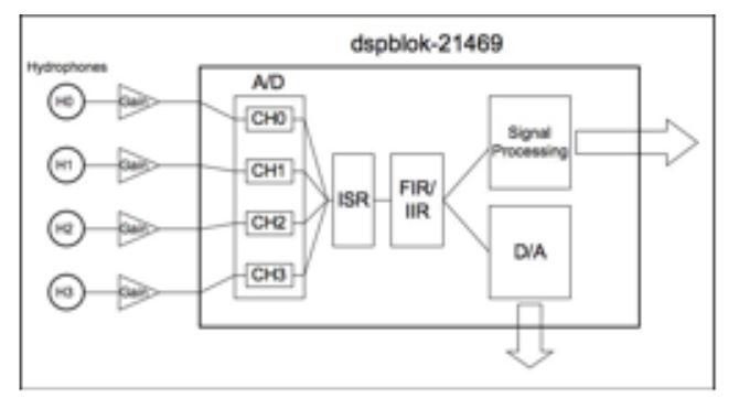
Fig. 2: USBL Acoustic Subsystem Flow Diagram
The USBL acoustic subsystem, shown in Fig. 2, obtains input from the external environment via an array of four RESON TC4013 Miniature Reference Omni-directional hydrophones. The piezoelectric sensor element contained inside the rubber nibble produces an electrical signal on the order of approximately 40mv, which propogates up the coaxial cable. The electrical signal is amplified to satisfy the requirements of the dspblok ad96k42 audio I/O platform.
HARDWARE SUBSYSTEM
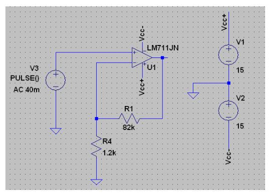
Fig. 3: 50x Amplifier Circuit Schematic
The signal produced by the hydrophones is approximately 40mV; however, the Wolfson WM8731 ADC on the dspblok ad96k42 platform requires a minimum input signal voltage of 1.8 V peak. In order to satisfy the requirement, I designed a simple 50x non-inverting amplifier, as shown in Fig. 3, using a LM711JN operational amplifier.
SOFTWARE SUBSYSTEM
The amplified signal is then input into the digital signal processor where the analog to digital converter converts the analog signal into a corresponding digital signal and stores the resulting signal representation before triggering a signal interrupt. The system catches the interrupt, pushes the stored input signal representation to the digital to analog converter and the resulting analog signal is output from the system.
TESTING
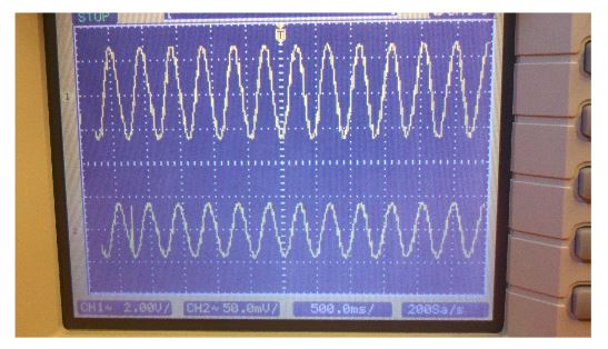
Fig. 4: Test signal amplification circuit on signals produced by function generator
The first step in testing the amplification circuit was to verify the gain factor by comparing the input signal produced by a function generator outputting a 40mV sinusoid signal against the signal output by the amplification circuit. As is shown in Fig. 4, the channel-2 signal is 40mV and the output signal labeled channel-1 is 2.4V which is approximately a 40x gain factor as was expected.
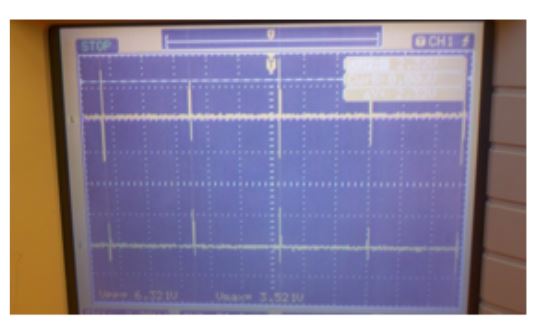
Fig. 5: Test signal amplification circuit using hydrophones
The next step was testing the amplification circuit using an input signal produced by the TC4013 hydrophone. Fig. 5 shows the change in amplification of the output signal from the input signal. The input signal while not consistent is on average greater than the 40mV expected input and the amplified signal remains above the minimum required voltage for the dspblok ad96k44 audio i/o board.
CONCLUSION
I was successful in demonstrating that the raw signal could be captured, filtered, and information about the signal could be delivered over the UART. However, I encountered some technical problems integrating the code written in assembly with other code written in C. These integration challenges prevented me from completing the end to end integration and testing required to achieve all the goals outline at the beginning of the project as Phase I.
Source: California Polytechnic State University
Author: Timothy Joel Soppet