ABSTRACT
Optical rectennas are antenna-coupled diode rectifiers that receive and convert opticalfrequency electromagnetic radiation into DC output. Because classical rectennas working at microwave frequencies can achieve very high rectification efficiencies, rectennas working as solar cells were expected to have efficiencies significantly higher than conventional solar cells.
By applying the theory of photon-assisted tunneling (PAT) to optical rectennas at solar intensities, I show that the power conversion efficiency of rectenna solar cells is fundamentally limited to the Trivich-Flinn efficiency limit of 44%. This unexpected result is the same as the Shockley-Queisser ultimate efficiency limit of conventional solar cells.
Is it possible to exceed this efficiency limit? I answer this question by showing that there is a correspondence between the quantum and classical operation of a rectenna. Such correspondence allows high frequency rectennas to operate in the same way as classical rectennas, and to potentially exceed the Trivich-Flinn efficiency limit. I propose two ways to achieve classical operation in optical rectennas.
Diode design is crucial for achieving high rectification efficiency. High-speed diodes, such as metal-insulator-metal (MIM) diodes, have insufficient asymmetry for harvesting low intensity radiation. I suggest steps to improve the characteristics of double insulator MIM diodes and calculate their power conversion efficiency using PAT theory. A simple figure of merit is provided to quickly assess the usefulness of MIM diodes in optical rectennas.
Although ineffective at visible frequencies, MIM diodes have RC time constants sufficient for operation at low terahertz frequencies, useful in applications including detection and high-speed electronics. I develop the steps to design MIM diodes at 1 THz, propose materials that will give the required current-voltage characteristics and RC time constant, perform electrical and optical measurements on fabricated devices, and suggest steps to improve their performance.
In contrast to MIM diodes, novel planar devices called geometric diodes have very low RC time constants and are capable of rectifying radiation up to 100 THz. I measure the infrared optical response of graphene-based geometric diodes, and demonstrate one of the best room-temperature detectors working at 28 THz.
HOW TO ANALYZE OPTICAL RECTENNA RESPONSE
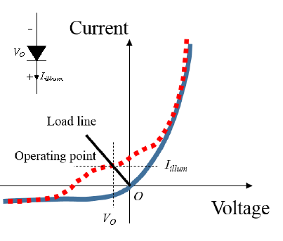
Figure I-3. Illustration of the illuminated I(V) characteristics of the diode in a rectenna.
Figure I-3. Illustration of the illuminated I(V) characteristics of the diode in a rectenna. The solid blue curve represents the dark I(V) characteristics of the diode and the dotted red curve represents the illuminated I(V) characteristics. The inset shows the sign of positive Iillum, corresponding to a diode dark current under positive bias, and the sign of VO, which is negative. In this mode, the diode generates DC power in the second quadrant of the diode I(V) characteristics. The load line intersects the illuminated I(V) curve at the operating point, and the load resistance is chosen to maximize the power delivered to it.
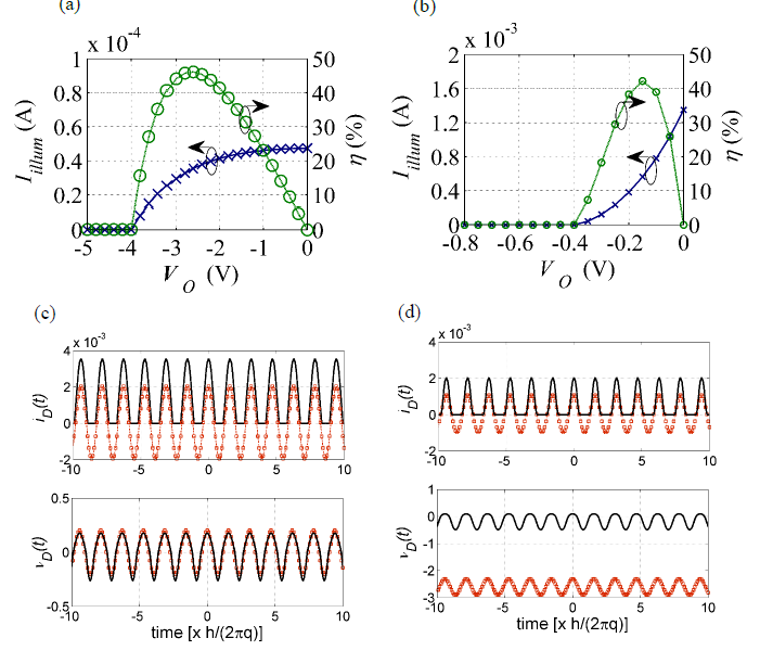
Figure I-5. Comparison of PAT and classical theory rectenna responses to high photon energy illumination (4 eV, corresponding to 310 nm), at two operating voltages for an input power of 200 μW.
Figure I-5. Comparison of PAT and classical theory rectenna responses to high photon energy illumination (4 eV, corresponding to 310 nm), at two operating voltages for an input power of 200 μW. The diode I(V) characteristics are the same as in figure I-4(a). Illuminated I(V) (blue crosses) and conversion efficiency (green circles) characteristics calculated using: (a) PAT theory and (b) classical theory. Classical theory gives incorrect results for this quantum case where VD < ℏω/q.
Also shown are plots of the time-dependent diode current (iD(t)) and diode voltage (vD(t)) calculated at (c) VO = 0 V using both PAT (red circles) and classical theories (solid black) and at (d) VO = –2.6 V for PAT theory and VO = –0.15 V for classical theory. The average of the diode currents in (d) gives the rectenna Iillum, shown in (a) and (b), and the chosen values for VO provide the maximum rectification conversion efficiency. This efficiency is not the ultimate efficiency of the rectenna in the quantum case, and can be improved using a diode that matches the antenna impedance at |VO| ~ ℏω/q.
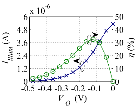
Figure I-6. Broadband illuminated I(V) and conversion efficiency characteristics of the diode in a rectenna calculated using PAT theory.
Figure I-6. Broadband illuminated I(V) and conversion efficiency characteristics of the diode in a rectenna calculated using PAT theory. The source is a blackbody of temperature 800 K, the input power to the rectenna is 1 μW, and the diode I(V) characteristics are the same as in figure I- 4(a). The Iillum (blue crosses) and conversion efficiency (green circles) calculated using PAT theory are shown as a function of VO. The maximum conversion efficiency is ~33 % for this diode I(V) and input conditions, and can be improved further using an I(V) characteristic that matches the antenna impedance at a negative operating voltage.
EFFICIENCY LIMITS OF RECTENNA SOLAR CELLS
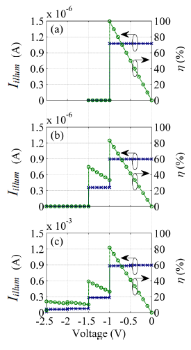
Figure II-2. Illuminated I(V) (blue crosses) and power conversion efficiency η (green circles) characteristics of the rectenna under monochromatic and two-frequency illumination.
Figure II-2. Illuminated I(V) (blue crosses) and power conversion efficiency η (green circles) characteristics of the rectenna under monochromatic and two-frequency illumination. (a) Monochromatic illumination. The incident photon energy is 1 eV, and the input power is 1.1×10– 6 W, corresponding to a solar power of 1000 W/m2 over an area with a radius of ~19 μm.
Rectenna efficiency approaches 100% when qVO approaches ћω. (b) Two frequency illumination corresponding to photon energies of 1 eV and 1.5 eV for the same total input power. The voltage amplitude of the two sources is equal and the fraction of the number of low to high energy photons is 1.5:1. (c) Same as (b), with increased input power corresponding to 103 suns, showing the appearance of tunneling current at high reverse operating voltages due to excitation of both higher order and mixing terms.
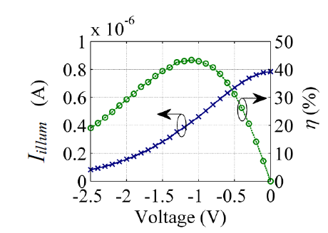
Figure II-3. Illuminated I(V) (blue crosses) and conversion efficiency (green circles) characteristics of the diode for an ideal rectenna under solar blackbody illumination at 5780 K.
Figure II-3. Illuminated I(V) (blue crosses) and conversion efficiency (green circles) characteristics of the diode for an ideal rectenna under solar blackbody illumination at 5780 K. The input power is 1.1×10⁻⁶ W. This is the maximum power available due to coherence issues, as described in the text. The diode dark I(V) characteristics have a shape like that shown in figure II-1(b), but with a slope and intercept designed for optimal power coupling from the antenna for each operating voltage. The maximum conversion efficiency is ~44%.
OPTICAL RECTENNA OPERATION: WHERE MAXWELL MEETS EINSTEIN
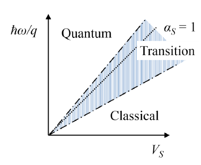
Figure III-1. Sketch of the operating regimes of a rectenna as a function of the source voltage.
Figure III-1. Sketch of the operating regimes of a rectenna as a function of the source voltage (VS = √ 8PmRs) and the photon energy divided by the electronic charge (ℏω/q). Classical operation occurs when VS ≫ ℏω /q, whereas quantum operation occurs when VS < ℏω/q. The ratio of VS to ℏω/q is αS, and the hatched blue area around the αS = 1 line (dotted line) is the transition regime.
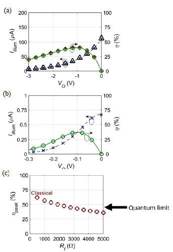
Figure III-5. Comparison of classical and quantum operation for rectennas under broadband illumination from a blackbody of temperature 600 K.
Figure III-5. Comparison of classical and quantum operation for rectennas under broadband illumination from a blackbody of temperature 600 K, showing I(V) (blue crosses) and conversion efficiency (green circles) characteristics. The diode is a piecewise linear diode with zero reverse leakage current. (a) Classical operation of the rectenna occurs at large Pin and RS (when Pin = 100 μW, Rf = 3 kΩ, and RS = 10 kΩ) giving high VS (rms) compared to the ℏω/q at which the blackbody spectrum peaks, and the results superimpose over the classical theory results (red pluses and black triangles).
The peak conversion efficiency (ηpeak) is 42%. (b) Quantum operation of the rectenna occurs at small Pin = 100 nW and RS = 100 Ω (Rf = 30 Ω). The rectenna operates efficiently over a smaller range of VO compared to the classical case and the resulting peak conversion efficiency is lower at 37.5%. (c) Variation of the peak conversion efficiency (ηpeak) of the rectenna (red circles), calculated using classical theory, with change in the diode Rf. Broadband classical operation is more efficient than quantum operation of the rectenna where the ultimate conversion efficiency is 44%.
DESIGN OF METAL/MULTI-INSULATOR/METAL DIODES FOR OPTICAL RECTENNAS
![Figure IV-2. The effect of changing diode parameters on MIIM diode current density vs. voltage [J(V)] and asymmetry (ratio of diode forward current to the reverse current) characteristics.](http://ece-eee.final-year-projects.in/wp-content/uploads/2017/09/p-2528-design-of-stacked40.png)
Figure IV-2. The effect of changing diode parameters on MIIM diode current density vs. voltage [J(V)] and asymmetry (ratio of diode forward current to the reverse current) characteristics.
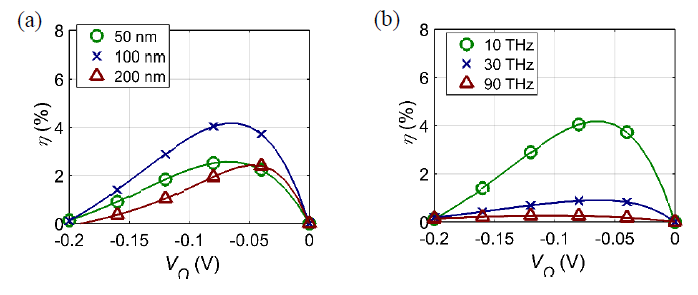
Figure IV-4. Effect of leakage current and the limited RC time constant on the efficiency (η) vs.
Figure IV-4. Effect of leakage current and the limited RC time constant on the efficiency (η) vs. VO characteristics of the step MIIM diode 3B described in figure IV-2, with CD ~17 fF/μm2. (a) η vs. VO characteristics of the rectenna for changing diode edge-length from 50 nm to 200 nm ( f = 10 THz, Pin = 100 μW). The ηpeak increases with increase in size to 100 nm but decreases at 200 nm due to increased reverse leakage. (b) η vs. VO characteristics for changing f from 10 THz to 90 THz (edge length 100 nm, and Pin = 100 μW). The ηpeak decreases as the frequency increases due to decrease in the coupling efficiency.
SIMPLE FIGURE OF MERIT FOR OPTICAL RECTENNA ANALYSIS
![Figure V-3. Illustration of the energy-band diagram and the calculated current density vs. voltage [J(V)] characteristics of resonant and step MIIM diodes.](http://ece-eee.final-year-projects.in/wp-content/uploads/2017/09/p-2528-design-of-stacked42.png)
Figure V-3. Illustration of the energy-band diagram and the calculated current density vs. voltage [J(V)] characteristics of resonant and step MIIM diodes.
(b) J(V) characteristics of the resonant MIIM diode for the parameters in (a), calculated using the method presented in reference [(Grover and Moddel, 2012a)] that uses the transfer matrix method to solve for the Schrodinger equation. (c) Energy-band diagram of the step diode for the barrier heights and insulator thicknesses indicated in the figure. The Δϕ = 0 eV, and the relative permittivities of I1 and I2 are 100 and 1, respectively. (d) The J(V) characteristics of the step MIIM diode for the conditions given in (c). The effective mass of the electron in the insulators is assumed to be its rest mass.
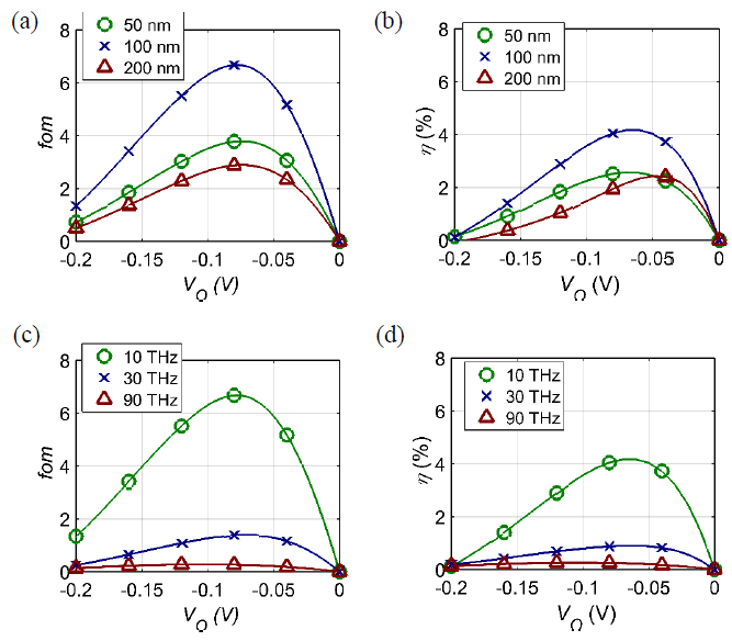
Figure V-5. Figure of merit (FOM) and conversion efficiency (η) vs. VO characteristics for the step MIIM diode shown in figure V-3(d), with CD ~17 fF/μm2.
Figure V-5. Figure of merit (FOM) and conversion efficiency (η) vs. VO characteristics for the step MIIM diode shown in figure V-3(d), with CD ~17 fF/μm2. The results follow the same trend as the resonant MIIM diode results shown in figure 4. (a) FOM vs. VO characteristics of the rectenna for increasing diode edge-length from 50 nm to 200 nm keeping f = 10 THz, and Pin = 100 μW, and (b) conversion efficiency vs. VO characteristics of the rectenna calculated using photon-assisted tunneling PAT theory, for the same conditions as in (a). (c) FOM vs. VO characteristics for increasing f from 10 THz to 90 THz and keeping an edge length of 100 nm and Pin = 100 μW, and (d) η characteristics calculated using photon-assisted tunneling PAT theory, under the same conditions as in (c).
METAL-INSULATOR-METAL DIODES FOR TERAHERTZ DETECTION
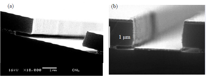
Figure VI-5. Cross-section scanning electron micrograph of the bilayer resist pattern.
Figure VI-5. Cross-section scanning electron micrograph of the bilayer resist pattern. (a) The bilayer resist pattern showing the undercut in the SF5 under-layer resist (~300 nm thick) beneath the SPR3012 photoresist pattern (~1 μm thick), and (b) bilayer resist pattern with evaporated nickel (~60 nm thick). The undercut allows for better lift-off of the metal with the photoresist.
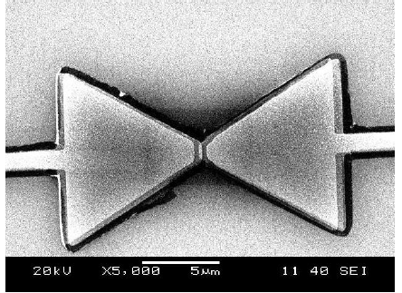
Figure VI-8. A scanning electron micrograph (SEM) of the Ni/NiO/Ni rectenna fabricated using the germanium shadow mask process.
Figure VI-8. A scanning electron micrograph (SEM) of the Ni/NiO/Ni rectenna fabricated using the germanium shadow mask process. The diode junction is at the center where the two arms of the bowtie antenna meet. This bowtie antenna shown here is designed for 1 THz radiation in a medium designed for heat harvesting, not for 1 THz radiation in free space. The device was fabricated by Bradley Pelz.
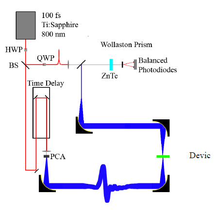
Figure VI-11. Setup for generating terahertz waves.
Figure VI-11. Setup for generating terahertz waves. The source is a 100 fs Ti:Sapphire laser that excites a biased photoconductive antenna (PCA) made of a dipole antenna on a GaAs wafer. Incident laser excites electrons across the two arms of the dipole antenna to modify the shape of the 100 fs pulse and generate terahertz waves. This setup was assembled by Zachary Thacker at the University of Missouri-Columbia. Image courtesy of Zachary Thacker.
INFRARED OPTICAL RESPONSE OF GEOMETRIC DIODE RECTENNAS
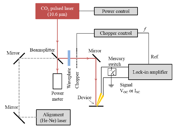
Figure VII-4. Setup for optical response measurement of geometric diode rectennas.
Figure VII-4. Setup for optical response measurement of geometric diode rectennas. The CO2 laser emits a 28 THz beam that is directed to the device using a set of mirrors. The beam is aligned with the device using a He-Ne laser. The device current and voltage response is measured using two probes and the output is sent to a lock-in amplifier that is locked in to the laser chopping frequency. A half-wave plate is used to study the polarization response of the rectenna by rotating the polarization of the beam.
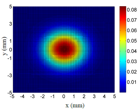
Figure VII-5. Intensity (W/mm2) profile of the 28 THz laser beam, obtained by measuring the power near the device as a function of distance (in mm) and fitting to a Gaussian profile.
The spatial intensity of the laser beam fitted to the measured power using a Gaussian profile is shown in figure VII-5. The laser intensity at the device was estimated to be ~50 mW/mm2, assuming the device was 1-2 mm offset from the center of the laser beam. Figure VII-5. Intensity (W/mm2) profile of the 28 THz laser beam, obtained by measuring the power near the device as a function of distance (in mm) and fitting to a Gaussian profile. The peak intensity at the center of the beam is ~80 mW/mm2.
CONCLUSIONS AND FUTURE WORK
The goal of my thesis research was to analyze the performance limits of optical rectennas for detection and energy harvesting. I worked towards the goal by applying the quantum theory of photon-assisted tunneling (PAT) and developing a method to calculate the optical response of a diode in a rectenna using a simple equivalent electrical circuit.
By studying the response of rectennas in the energy harvesting mode and solving for the time-dependent diode currents and voltages using PAT theory, I calculated the power conversion efficiency limits of rectennas under monochromatic illumination and when used as solar cells. I found that for diodes that are optimally matched to antennas, monochromatic power conversion efficiencies approach 100% and the multispectral efficiency is limited to 44% at solar terrestrial intensities, which is the same as the ultimate efficiency of conventional solar cells.
Developing the rectenna PAT theory further, I found that there is a correspondence between the quantum and the classical approaches. Rectennas follow Einstein’s photon-based approach if the amplitude of the diode voltage (VD) is less than the photon energy divided by the electronic charge (ℏω/q), and follow Maxwell’s classical electromagnetic wave nature of light if VD ≫ ℏω/q.
The correspondence between classical and quantum operation of the rectenna allows classical operation at optical and IR frequencies for high incident intensity and for large source and diode impedances. This is useful to improve the conversion efficiency of broadband rectennas for harvesting blackbody radiation, including solar radiation, beyond the quantum limit. The power conversion efficiency of solar rectennas can exceed the 44% limit for conventional semiconductor solar cells if classical operation can be achieved.
Source: University of Colorado
Authors: Saumil Joshi