ABSTRACT
Light Emitting Diode (LED) lamps are becoming the preferred lighting option for a large number of applications due to their high efficiency and long life. Since LED lamps require a power electronic driver to operate from ac line, the LED driver must also have a long life to take full advantage of the LED’s longevity. However, the life of offline LED drivers is constrained by the use of limited-life electrolytic capacitors, as twice-line-frequency energy buffers, in them. Twice-line-frequency energy buffering is needed in all high power factor power electronic interfaces between single-phase ac and dc.
The recently proposed Stacked Switched Capacitor (SSC) energy buffer architecture with film or ceramic capacitors can increase the life of single-phase ac-dc converters by eliminating electrolytic capacitors, while keeping the passive volume of the relatively lower energy density film/ceramic capacitors in check. This thesis presents a methodology for further increasing the effective energy density of enhanced unipolar SSC energy buffers by optimizing the capacitance ratio of the capacitors used in the energy buffer.
It is shown that the relative enhancement in energy density depends on the required ripple ratio and the number of supporting capacitors in the energy buffer. The presented methodology is validated using a 1-2 enhanced unipolar SSC energy buffer designed for an 8-W offline LED driver. This thesis also develops a method for precharging the capacitors in the SSC energy buffer that does not require a separate precharge circuit and presents new ground-referenced gate drive circuits suitable for low voltage enhanced unipolar SSC energy buffers.
STACKED SWITCHED CAPACITOR ENERGY BUFFERS
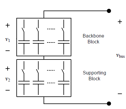
Figure 2-1: Basic architecture of a Stacked Switched Capacitor (SSC) energy buffer.
A Stacked Switched Capacitor (SSC) energy buffer consists of two seriesconnected blocks of switches and capacitors (referred to as backbone and supporting blocks), as shown in Fig. 2-1. Its operational principle is based on allowing the voltages across each block and each individual capacitor to vary across a wide range as the energy buffer is charged and discharged (enabling a large fraction of the energy stored in it to be utilized for buffering), but at the same time have the voltage variations across the two blocks compensate for each other; hence, keeping the dc bus voltage within the desired narrow range.
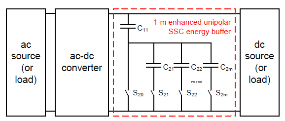
Figure 2-2: Enhanced unipolar Stacked Switched Capacitor (SSC) energy buffer connected across the dc port of a single-phase ac-dc converter.
Figure 2-2: Enhanced unipolar Stacked Switched Capacitor (SSC) energy buffer connected across the dc port of a single-phase ac-dc converter. This SSC energy buffer has one backbone capacitor and m supporting capacitors and is referred to as the 1-m. Figure 2-2 shows the topology of a 1-m enhanced unipolar SSC energy buffer connected across the dc port of a single-phase ac-dc converter. The 1-m SSC energy buffer has one backbone capacitor (C11), m supporting capacitors (C21, C22,…, C2) and (m+1) supporting switches (S20, S21,…, S2).
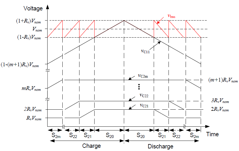
Figure 2-3: Normal operation voltage waveforms for a 1-m enhanced unipolar SSC energy buffer.
Figure 2-3: Normal operation voltage waveforms for a 1-m enhanced unipolar SSC energy buffer with equal capacitances during the discharge period, assuming constant current discharge. Waveforms shown include the dc bus voltage , and the voltages across the backbone capacitor 11 and all the supporting capacitors (21 to 2).
CAPACITANCE RATIO OPTIMIZATION
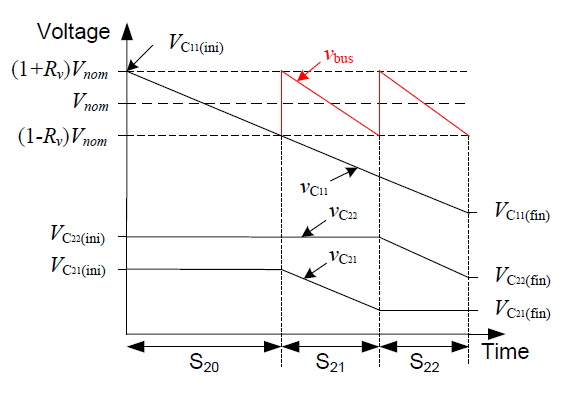
Figure 3-3: Normal operation voltage waveforms for a 1-2 enhanced unipolar SSC energy buffer.
Figure 3-3: Normal operation voltage waveforms for a 1-2 enhanced unipolar SSC energy buffer with unequal capacitances during the discharge period, assuming constant current discharge. Waveforms shown include the dc bus voltage , and the voltages across the backbone capacitor 11 and all the supporting capacitors (21 to 22).
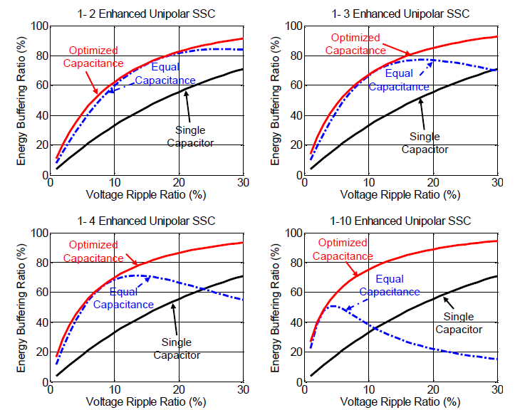
Figure 3-14: Energy buffering ratio as a function of ripple ratio.
Figure 3-14: Energy buffering ratio as a function of ripple ratio for the 1-2, 1-3, 1-4 and 1-10 enhanced unipolar SSC energy buffers with optimized capacitance ratios (red solid line) versus equal capacitance (blue dashed line). Energy buffering ratio of a single capacitor is also provided for comparison (black solid line).
PROTOTYPE DESIGN AND EXPERIMENTAL RESULTS
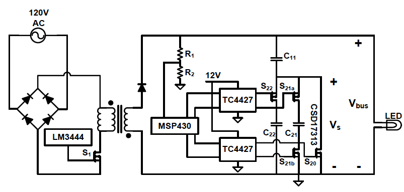
Figure 4-2: Switch, gate-drive and control implementation of the prototype 1-2 enhanced unipolar SSC energy buffer as part of the offline LED driver.
The schematic of the 1-2 enhanced unipolar SSC energy buffer, as part of the LM3444 LED driver, is shown in Fig. 4-2. One of the switches (S21) in the 1-2 enhanced unipolar SSC energy buffer needs to be a four quadrant switch, while the other two switches (S20 and S22) need only be two quadrant. To limit the complexity of the overall SSC energy buffer, it is important to have a simple and reliable gate drive circuit for these switches.
Next a model for the LM3444 LED driver with a 1-2 enhanced unipolar SSC energy buffer is developed in PLECS, as shown in Fig. 4-5. Note that the SSC energy buffer replaces capacitors C3 and C4. Two version of the SSC energy buffer are developed; one with capacitors of equal capacitance value and the other with capacitors having optimal capacitance ratios.
SUMMARY, CONCLUSIONS AND FUTURE WORK
This thesis investigates opportunities for further size reduction in ceramic capacitor based Stacked Switched Capacitor (SSC) energy buffers suitable for single-stage offline LED drivers. The motivation for this work comes from the need to eliminate limited-life electrolytic capacitors (used as twice-line-frequency energy buffers) from offline LED drivers, in order to match the life of the drivers to the long life of the LED lamps.
SSC energy buffers have recently been proposed as an alternative twice-linefrequency energy buffering architecture. They utilize long-life lower-energy-density film or ceramic capacitors, instead of electrolytic capacitors, without incurring a size penalty. They work on the principle of having their two series-connected blocks of switches and capacitors charge and discharge in such a way that the voltage variations across the individual blocks compensate for each other and keep the dc bus voltage within a desired narrow range.
Hence, by allowing wide voltage variations across the individual blocks and the individual capacitors, a large fraction of the energy stored in the energy buffer can be utilized for buffering while maintaining a narrow range dc bus voltage. Detailed description of the different types of SSC energy buffers developed to date is provided in Chapter 2. The SSC energy buffer that is selected for further investigation in this thesis is the enhanced unipolar SSC energy buffer. The circuit topology and control of this SSC energy buffer is also described in Chapter 2.
Source: University of Colorado
Authors: Yu Ni
