ABSTRACT
The work done in this study concerns laser guided vehicles, and more specifically the autonomous navigation by following the edge of a road. The idea is that using two synchronized lasers on top of each other would increase the robustness of the road detection, compared to only one laser. The algorithm was developed in Matlab, using a sequence of scans recorded on a snowy road with snow piles on the sides.
The road detection uses the Hough transform for each scan. The relative position of the robot on the road is then estimated from the road edges detections. The control law is based on the “dog-rabbit principle”. Simulations were done in Matlab, and a few tests have also been done on the MICA wheelchair. The algorithm was successful when following a straight corridor, but some more work has to be put into dealing with intersections, and on predicting the detection.
THE MOBILE ROBOT AND THE MOTION EQUATIONS
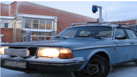
Figure 2 : The car with the 360 laser scanner on the roof
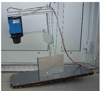
Figure 3 : The laser scanner with now the mirror
The initial robot that was planned to be controlled in this project was a car with a 360 degrees laser scanner mounted on the roof, see Figure 2. A mirror placed behind the laser is used to produce a second laser scan, as shown on Figure 3. The steering should be automated, allowing the car to follow a road with edges (snow piles or building). The speed of the car is controlled by the driver. The practical test of controlling the car was done in another project; the object of this project was only the theory of implementing the steering algorithm.
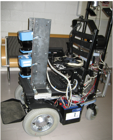
Figure 6 : The Mica wheelchair with the two lasers in the front
The robot used is the MICA (Mobile Internet Connected Assistant) wheelchair, see Figure 6. It can be remotely controlled, and has an embedded PC connected to the internet via WLAN. A great advantage with the wheelchair is that it is possible to get readings from the lasers and to send commands using Matlab. The algorithms developed in Matlab can then be tested directly on the robot.
THE LASER SCANNER AND ALGORITHM FOR FINDING LINES
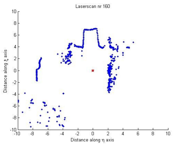
Figure 9 : Scan of a typical forest road with snow edges on both sides
Figure 9 : Scan of a typical forest road with snow edges on both sides. The road line is in the upper middle, the trees are the irregular pattern to the right, the lower left, and between the road and the building. The plot is in laser coordinates.
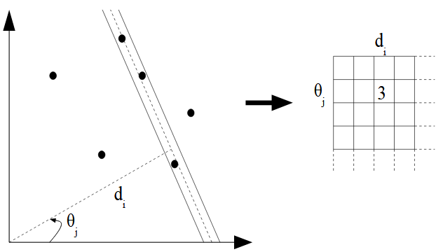
Figure 12 : The Hough transform counts the number of points in a strip around the line
Figure 12 : The Hough transform counts the number of points in a strip around the line defined by d and θ, and puts this number in the Hough matrix. The resulting transform is a two dimensional histogram. For each combination of d and θ in those intervals, the number of (x,y)-pairs in the image solving the above equation is put in the Hough matrix of size [Id x Iθ], see the grid in Figure 12.
FINDING THE POSITION OF THE ROBOT ON THE ROAD
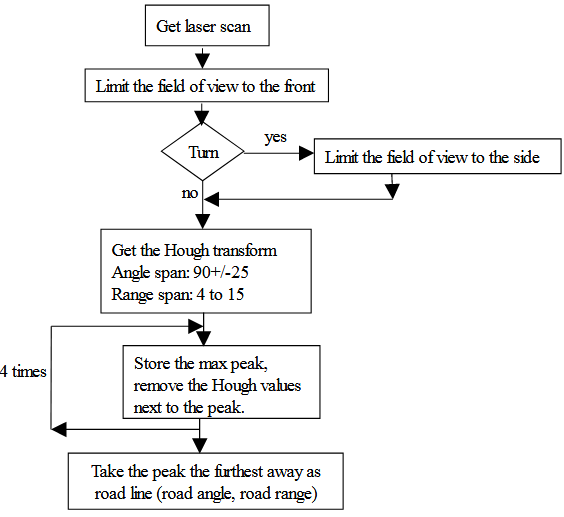
Figure 15 : Algorithm to find the road line using the Hough transform
Each of the four times, the highest peak is stored (its range and angle) and removed from the matrix, and the peaks too close to it are also deleted. This is done to avoid multiple Hough lines when the data line is “noisy”. An alternative solution could be to increase the step size, but then there is a loss in precision. The diagram in Figure 15 describes the algorithm used to find the Hough line.
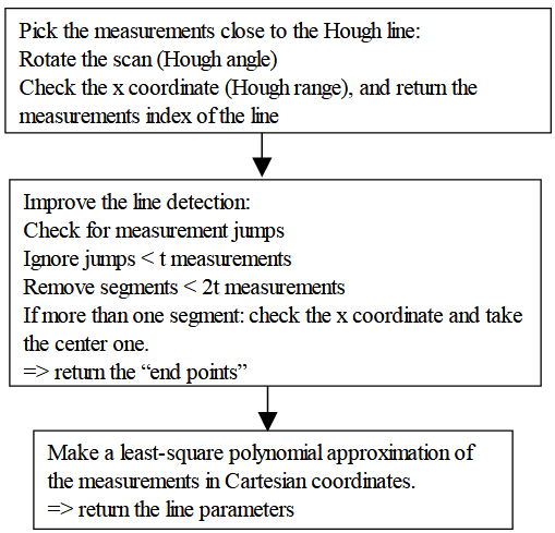
Figure 16 : Finding the road from the Hough line. The parameter t allows to adapt the algorithm to the test environment. In this study t=6
To be able to get the position of the robot on the road, we need to know where the road stops on the left and right sides. We first pick all the measurements of the scan lying close enough to the Hough line. Then, since the road is supposed to be a continuous line, we discard the isolated small segments of measurements, that are most probably not part of the road. A least-square polynomial approximation is done with the measurements of the remaining segment, and the first and last point of the polynomial are the road “end points” along the scan. This algorithm is more detailed on the diagram on Figure 16.
THE CONTROL LAW AND SIMULATIONS
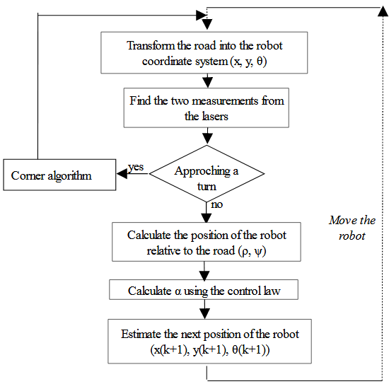
Figure 23 : Block diagram of the simulation, for a robot following a line by the right side. Two lasers are used to detect this line
The different steps in the simulation are shown in the Figure 23. The part about the left turn detection will be explained later in section, and skipped for now. The line to be followed is simulated by a set of points in global coordinates. The laser rays are also simulated by a set of points, in the robot coordinate system.
IMPLEMENTATION AND TESTING IN THE WHEELCHAIR
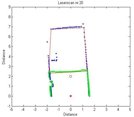
Figure 30 : Detected road-lines and walls in the corridor. The calculated aim point is plotted as the small circle
In Figure 30 below is one of the scan of the sequence when the robot was driving autonomously. We can see that the left wall became a bit shifted because of a bench in the way of the front laser, in blue. This indicates that obstacle avoidance might be possible to implement using this algorithm.
EVALUATION AND DISCUSSION
The goal of this master thesis has been to investigate the idea of using two synchronized laser scanners on a mobile robot to navigate on a road with some kind of edge (snow, building, wall,…). This in order to increase the robustness of the road detection compare to using only one laser.
The work done covered the development an algorithm to find the needed information about the road position in the laser scans, and the simulation of the control law. The algorithm has been tested somehow successfully in the wheelchair, but more tests need to be done.
The results are highly dependant on the type of environment where the robot is driving. Since the algorithm has been developed for a snowy road in the forest, the tests on the robot in other environments might not give the same good results. Some model based adjustments should be done of the algorithm.
Source: Luleå University of Technology
Authors: Marion Billaux
>> Automobile based Matlab Project Topics with Free Base Papers Downloads
>> 200+ Matlab Projects based on Control System for Final Year Students