ABSTRACT
To address the various emerging standards like Bluetooth TM, Home RF, Wi-fi TM (IEEE 802.11), ZigBee TM etc., in the field of wireless communications, different transceivers have been designed to operate at various frequencies such as 450 MHz, 902-920 MHz, 2.4 GHz, all part of designated ISM band.
Though, the wireless systems have become more reliable, compact and easy to develop than before, a detailed performance analysis and characterization of the devices should be done. This report details the performance analysis and characterization of a popular binary FSK transceiver TRF6901 from Texas Instruments. The performance analysis of the device is done with respect to the TRF/MSP430 demonstration and development kit.
WIRELESS TRANSCEIVERS
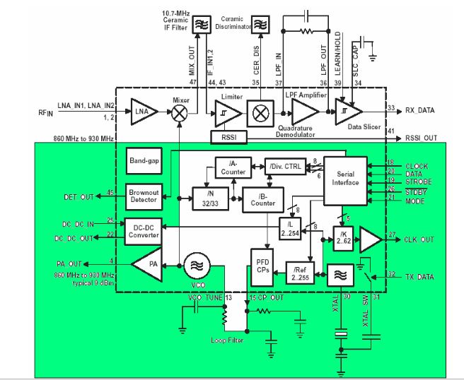
Figure 3: TRF6901 Transmitter block diagram
The transmitter consists of an integrated VCO (voltage con trolled oscillator) and a tank circuit, a complete integer-N synthesizer, and a PA (power amplifier). The divider, pre-scaler and reference oscillator require only the addition of an external crystal and a loop filter to provide a complete PLL (phase locked loop) with a typical frequency resolution of better than 200 KHz. These are shown in figure 3.
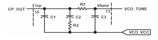
Figure 5: External Loop Filter
The loop filter is typically a second or third-order passive design. The bandwidth of the filter should be wide in-order to relock the PLL as the FSK frequency is toggled when sending data. The loop filter should also be wider than the data modulation rate. Figure 5 shows a typical third order passive filter circuit.
RANGE ESTIMATION
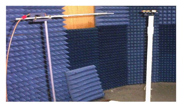
Figure 17: Experimental Set up of on board PCB antenna of TRF6901 Demonstration
The single axis rotational pattern technique was employed for the pattern measurement of the PCB antenna. The AUT, i.e., the TRF6901 demonstration and development kit configured in transmitting mode was placed on a rotational positioner and rotated about the azimuth to generate a two dimensional polar pattern. The measurement was accomplished by using a Yagi antenna as a measuring antenna (MA). Figure 17 shows a typical test set up.
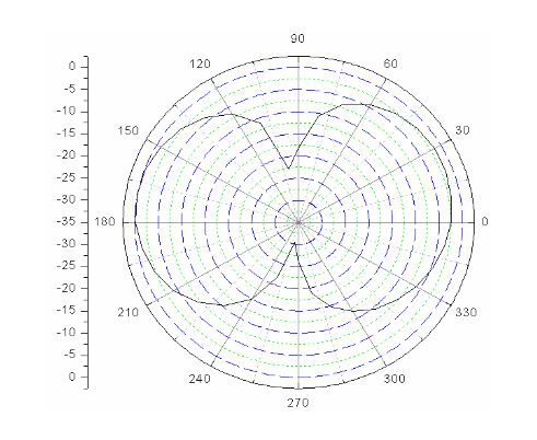
Figure 28: Cross-polarization pattern
The TRF board is in vertical position with the Yagi antenna in horizontal position separated by a distance of 86 cm and 87 cm above the ground. Figure 28 shows the measured pattern. Table 8 contains the measured data.
CONCLUSION
A wireless device needs to be tested comprehensively before being put in an application. Communication range is an extremely important factor in characterizing a wireless device. This work characterized a wireless transceiver, with special emphasis on TRF6901, with respect to the TRF6901/MSP430 demonstration and development board. The board with RF section as TRF6901 and its matching components driven by a base-band processor MSP430, employs an inverted-F antenna(IFA).
Since the antenna characteristics were not provided by the supplier, a detailed design analysis of the employed antenna was done by simulating in IE3D, a commercial method of moment software packages from Zeland. The simulation results were verified by taking experimental measurements in the laboratory environment, a semi-anechoic chamber. It is seen that the employed antenna has the ability to receive both horizontally and vertically polarized electromagnetic waves. For indoor environments where the depolarization phenomenon makes the choice of polarization difficult, this type of antenna can be the best possible choice.
The range of the board was also measured with an external sleek dipole antenna with a relatively higher gain than the on-board pcb antenna. It shows that there is a slight benefit of the external dipoles over the IFAs. Although, many wireless devices use the vertically polarized antennas, it was found that using horizontal polarization both at the receiver and at the transmitter results in 10 dB more power in the median than using vertical polarization both at the receiver and the transmitter
Source: University of Central Florida
Author: Usha Neupane
>> Simple Internet of Things (IoT) Diy Projects
>> More Wireless Bluetooth Projects for Final Year Students
>> More Wireless Hacking Projects for Wi-fi Enthusiasts for Engineering Students
>> More Wireless Projects Using Zigbee for Final Year Students