ABSTRACT
This paper proposes a radiating pattern reconfigurable antenna by employing RF Micro-electromechanical Systems (RF MEMS) switches. The antenna has a low profile and small size of 4 mm × 5 mm × 0.4 mm, and mainly consists of one main patch, two assistant patches, and two RF MEMS switches. By changing the RF MEMS switches operating modes, the proposed antenna can switch among three radiating patterns (with main lobe directions of approximately −17.0◦, 0◦ and +17.0◦) at 35 GHz. The far-field vector addition model is applied to analyze the pattern. Comparing the measured results with analytical and simulated results, good agreements are obtained.
PATTERN RECONFIGURABLE ANTENNA STRUCTURE AND DESIGN
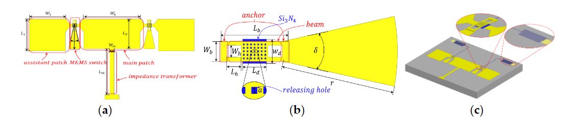
Figure 1. Proposed radiating pattern reconfigurable antenna using micro-electromechanical systems (MEMS) switches
A strategy for a radiating pattern reconfigurable antenna is proposed, the structure is illustrated in Figure 1a, and the optimized geometry of the RF MEMS switch is shown in Figure 1b. The pattern reconfigurable antenna—fabricated on a high resistivity silicon substrate with a relative dielectric constant of 11.9 and thickness of 400 μ m—consists of one rectangular main patch radiator, two rectangular assistant patch radiators, one impedance transformer, and two RF MEMS switches.
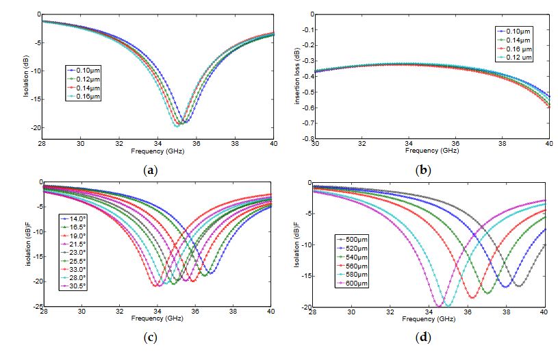
Figure 3. The relationship between resonant frequency
In order to select the optimized parameters of the RF MEMS switch, some simulations of the switch were conducted under the conditions of various parameter combinations. The resonant frequency of the RF switch (in the down state) raises with the increase of the degree of sector stub, with the increase of the dielectric thickness and with the decrease of the radius of the sector stub, as shown in Figure 3.
THEORY ANALYSIS
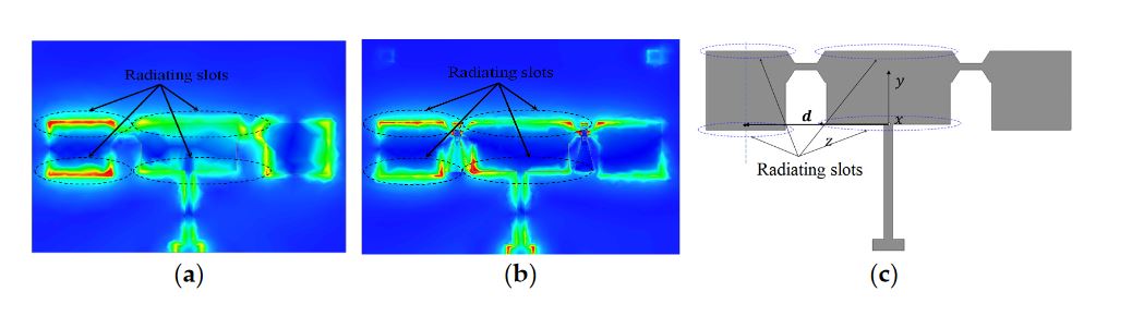
Figure 5. Distribution of the surface electric field of the antenna, when the left switch is in the up state and the right is in the down state
Instead, plotting the electric fields on the patch, the electric field vector addition method is employed in the far-field region to evaluate far-field distribution. Figure 5a shows the distribution of the electric field while the RF MEMS switches were replaced by conductor patches, in order to simplify the complexity of radiating problems.
In contrast, the electric field distribution of an antenna using RF MEMS switches was demonstrated in Figure 5b, and one can conclude that the electric field distribution is almost unchanged by RF MEMS switches. The differences between Figures 5a and 5b are mainly caused by the impact of sector stubs, but the maximum of the distribution of the electric field is almost unchanged and has no effect on the analysis process for the rest of this paper.
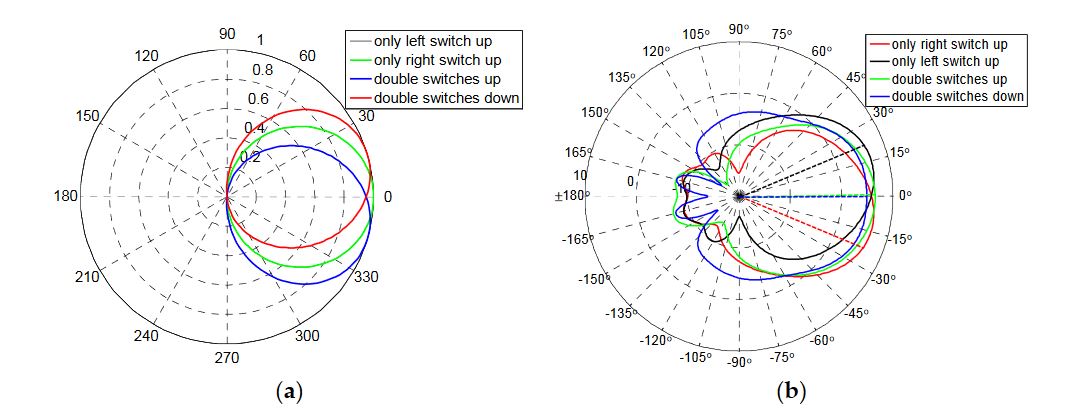
Figure 6. Radiation patterns of reconfigurable antenna. (a) Theoretical evaluation of patterns; (b) Simulation of patterns
The magnetic field can also be expressed according to the electromagnetic relationship of plane wave in the free space or Maxwell equations. Here to, the radiating patterns were obtained and can be plotted using MATLAB software (MATLAB 7.10, The Mathworks, Natick, MA, USA) as shown in Figure 6a. Comparing the theoretical evaluation patterns with the simulation patterns, good agreements of maximum radiating directions are obtained.
RESULTS AND DISCUSSION
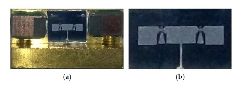
Figure 7. Photograph of the proposed antenna. (a) Antenna with testing holder; (b) Pure antenna fabricated on high resistivity silicon
In this paper, the proposed pattern reconfigurable antenna was simulated by HFSS software (HFSS13.0, Anosoft, Pittsburgh, PA, USA), and the results are presented in Figure 6b. Photographs of the antenna are shown in Figure 7. The proposed antenna was measured by the network analyzer Agilent PNA N5442A (10 MHz–43.5 GHz) (Agilent, Santa Clara, CA, USA).
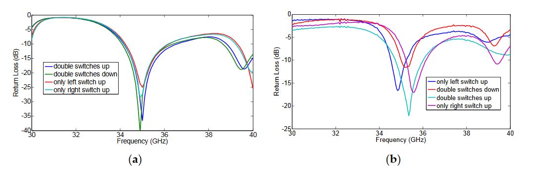
Figure 8. The measured return losses of all modes. (a) Simulation; (b) Measurement
The simulated return loss of all modes at the desired frequency are all greater than 20 dB, as shown in Figure 8a. As shown in Figure 8b, the measured return losses of all modes are greater than 10 dB. The discrepancies between the measured results and the simulated ones are mainly caused by conductor loss and the manufacture process, such as the lithographic resolution, the residual polyimide, the inhomogeneity of thickness, and the asymmetry between the left RF MEMS switch and the right RF MEMS switch.
CONCLUSIONS
This paper introduces the design and analysis of a Ka-band pattern reconfigurable patch antenna using RF MEMS switches. A planar antenna with a pattern reconfigurable characteristic is presented for the sake of verification of proposed method. By changing the states of the RF MEMS switches, three reconfigurable radiating patterns are obtained—i.e., left (approximately − 17◦), middle (approximately 0◦), and right (approximately +17◦), respectively. Due to the small size and lightweight characteristics, the proposed pattern reconfigurable antenna is an excellent candidate for satellite searching, tracing, and communication systems.
Source: Beijing University
Authors: Zhongliang Deng | Xubing Guo | Hao Wei | Jun Gan | Yucheng Wang
>> 60+ Antenna Communication Projects for Engineering Students
>> Antenna Design Projects using Matlab for ECE Students with Source Code
>> Antenna Projects Using HFSS for ECE Final Year Students
>> Smart Antenna Design Final Year Projects for Engineering Students