ABSTRACT
Fiber-reinforced polymer (FRP) has been increasingly applied to steel structures for structural strengthening or crack repair, given its high strength-to-weight ratio and high stiffness-to-weight ratio. Cracks in steel structures are the dominant hidden threats to structural safety. However, it is difficult to monitor structural cracks under FRP coverage and there is little related research. In this paper, a crack monitoring method for an FRP-strengthened steel structure deploying a microstrip antenna sensor is presented.
A theoretical model of the dual-substrate antenna sensor with FRP is established and the sensitivity of crack monitoring is studied. The effects of the weak conductivity of carbon fiber reinforced polymers (CFRPs) on the performance of crack monitoring are analyzed via contrast experiments. The effects of FRP thickness on the performance of the antenna sensor are studied. The influence of structural strain on crack detection coupling is studied through strain–crack coupling experiments. The results indicate that the antenna sensor can detect cracks in steel structures covered by FRP (including CFRP). FRP thickness affects the antenna sensor’s performance significantly, while the effects of strain can be ignored. The results provide a new approach for crack monitoring of FRP-strengthened steel structures with extensive application prospects.
CRACK MONITORING MECHANISM OF DUAL-SUBSTRATE ANTENNA SENSOR
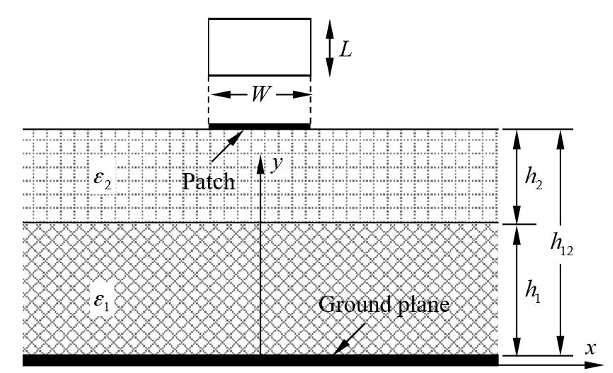
Figure 1. Cross-section of dual-substrate antenna sensor
Figure 1 shows the cross-section of the dual-substrate antenna sensor, where L and W are the length and width of the patch, respectively; ε1 and ε2 are the relative dielectric constants of the FRP and the substrate, respectively; h1 and h2 denote the thicknesses of the FRP layer and the substrate, respectively; and h12 is the distance from the ground plane surface to the substrate surface.
NUMERICAL INVESTIGATION
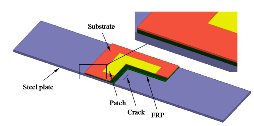
Figure 2. Multi-sectional view of the dual-substrate antenna sensor
The antenna design was simulated using the commercial electromagnetic simulation software HFSSTM, and the crack monitoring model of the dual-substrate antenna is shown in Figure 2. An antenna sensor without a ground plane is arranged on the top surface of the FRP to form a dual-substrate antenna sensor with four “steel plate-FRP-substrate-patch” layers.
SENSITIVITY ANALYSIS OF ANTENNA SENSORS FOR CRACK MONITORING
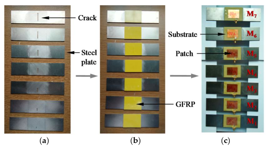
Figure 4. Specimen fabrication process stages: (a) steel plates with various crack lengths; (b) cracked steel plates when strengthened using glass fiber reinforced polymer (GFRP); (c) finished specimens
Figure 4 shows a sample production process, including (a) seven steel plates with crack lengths that differ with a step size of 4 mm; (b) cracked steel plates when strengthened by GFRP layers; (c) use of epoxy resin AB glue (supplied by Shenneng Adhesives Wholesale, Jinhua, China) to bond the antenna sensor on the GFRP surface and constitute a series of specimens denoted by M1–M7, with crack lengths of 4 mm, 8 mm, 12 mm, 16 mm, 20 mm, 24 mm, and 28 mm, respectively. A through crack with 0.5 mm width was cut by EDM (electrical discharge machining) for specimens M1 to M7 with a 0.002 mm machining accuracy.
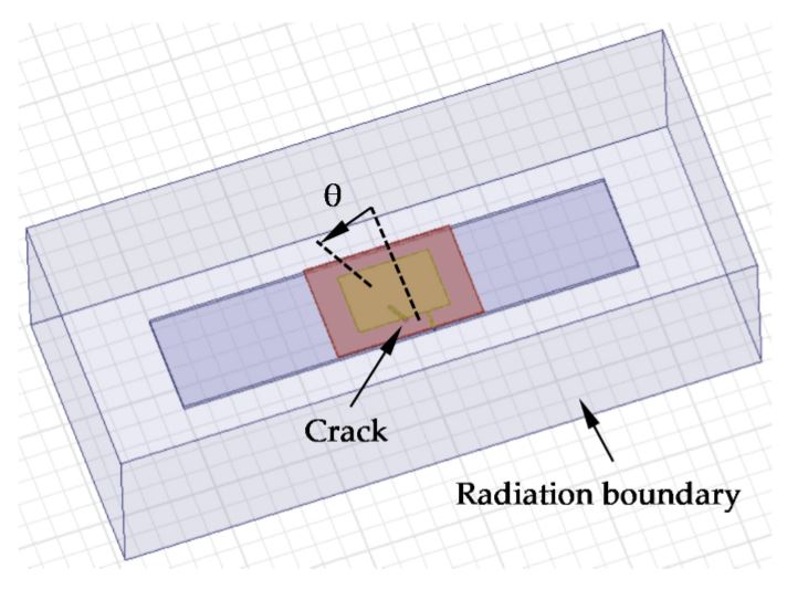
Figure 7. Simulation model for crack orientation
In Figure 7, the model parameters are all equal to those in Table 1; the crack length is 4 mm and the step size of θ, which represents the crack angle, is 15◦ in this set of numerical simulations.
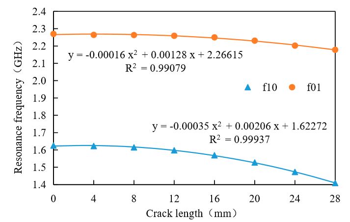
Figure 8. The relation between resonant frequency and crack length of oblique crack
It can be learned from Figure 8 that the results for oblique cracks are similar to those for straight cracks. The resonant frequency decreases with increasing crack length while the sensitivity of the antenna sensor increases with increasing crack length. When the crack length is 16 mm, the sensitivity of TM10 and TM01 are 3.84 MHz/mm and 9.14 MHz/mm, respectively, which indicates that the antenna sensor designed in this paper still has a high sensitivity for oblique crack identification.
INFLUENCE OF FRP PROPERTIES ON CRACK MONITORING
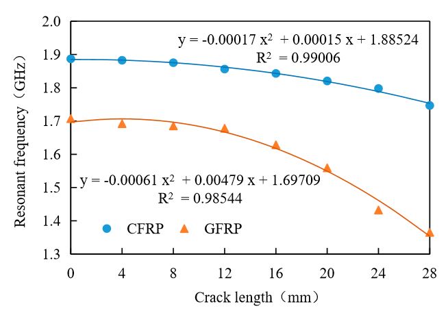
Figure 10. Experimental results for CFRP and GFRP
Figure 10 also shows that the resonant frequency offset obtained in the CFRP experiment is significantly smaller than the corresponding offset for GFRP. Due to the effects of the conductivity of CFRP, the sensitivity of the antenna sensor for crack monitoring in CFRP-strengthened steel structures is lower than that for GFRP-strengthened steel.
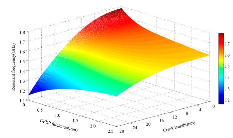
Figure 11. Resonant frequency–GFRP thickness–crack length characteristics in a 3D diagram
Figure 11 shows that when the crack is relatively short, the antenna sensor’s resonant frequency decreases with increasing FRP thickness; however, when the crack is relatively long, the resonance frequency of the antenna sensor then increases with increasing FRP thickness. When the crack length increases, the resonant frequency of the antenna sensor gradually decreases.
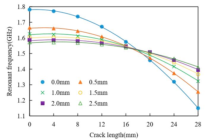
Figure 14. Relationship between resonant frequency and crack length for the different FRP thickness
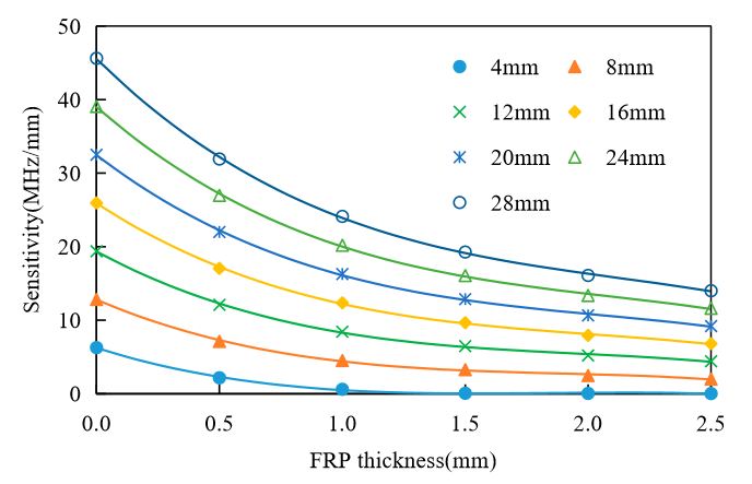
Figure 15. Effects of Fiber Reinforced Polymer (FRP) thickness on the antenna sensor’s sensitivity
Figure 15 shows that the sensitivity of the antenna sensor decreases gradually with increasing FRP thickness. For a crack with a length of 8 mm, the sensitivity of the antenna sensor is 7.13 MHz/mm when the FRP thickness is 0.5 mm, but when the FRP thickness increases to 2.5 mm, the sensitivity is reduced to 2.01 MHz/mm. For a crack with a length of 20 mm, the sensitivity of the antenna sensor is 22.01 MHz/mm when the FRP thickness is 0.5 mm, but when the FRP thickness increases to 2.5 mm, the sensitivity is then reduced to 9.21 MHz/mm. Sensors 2017, 17, 2394 14 of 17 antenna sensor is 22.01 MHz/mm when the FRP thickness is 0.5 mm, but when the FRP thickness increases to 2.5 mm, the sensitivity is then reduced to 9.21 MHz/mm.
EFFECTS OF STRAIN ON CRACK MONITORING
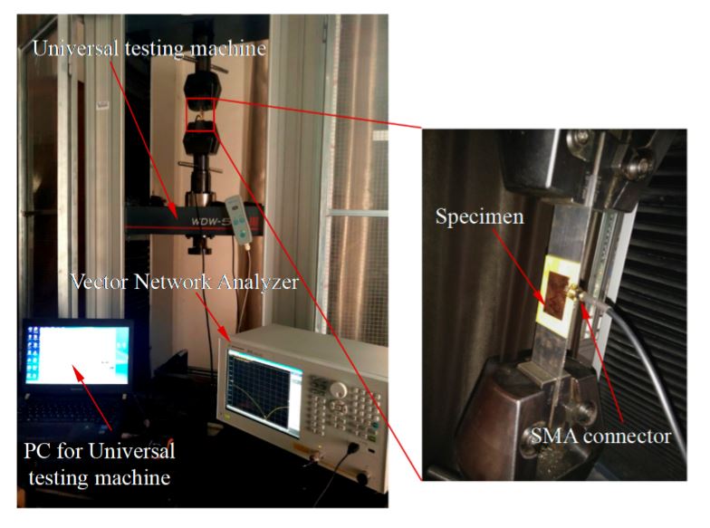
Figure 16. Experimental platform used for strain detection of antenna sensor
A strain measurement experiment was designed for the antenna sensor. The antenna sensors M1 to M7 were placed on the WDW-50E microcomputer controlled electronic universal testing machine to apply tension, as shown in Figure 16.
CONCLUSIONS
In this paper, an antenna-sensor-based method for the monitoring of crack damage in FRP-strengthened steel structures has been studied, and the conclusions are summarized as follows.
1. The antenna sensor can detect cracks in an FRP-strengthened steel structure. The resonant frequency decreases with increasing crack length, while the sensitivity of the antenna sensor increases with increasing crack length.
2. The weak conductivity of CFRP interferes with the test signal, but the effective resonance frequency offset can still be measured. The dual-substrate antenna sensor designed here is also suitable for use with CFRP-reinforced steel structures.
3. The FRP layer thickness has a significant influence on the antenna sensor’s resonant frequency. When the crack length is less than 17 mm (approximately 3/5 of the patch width), the sensor antenna resonant frequency decreases with increasing FRP thickness. However, when the crack lengthismorethan17mm,the antenna sensor’s resonant frequency the n increases with increasing FRP thickness.
4. The sensitivity of the antenna sensor used to monitor the cracking of FRP-strengthened steel structure decreases with increasing FRP thickness.
5. Strain has very little effect on the antenna sensor’s ability to monitor cracking under the FRP coverage.
FUTURE PROSPECTS
1. High frequency antenna sensors will be more sensitive to crack identification, and we will design higher frequency antenna sensors in future work.
2. The identification of multiple cracks by a single antenna sensor involves complex current distribution, which can be studied from the influence of multiple cracks on the antenna current path.
Source: Wuhan University of Technology
Authors: Zhiping Liu | Kai Chen | Zongchen Li | Xiaoli Jiang
>> Microstrip Patch Antenna using HFSS for ECE Final Year Students
>> Final Year Project on Microstrip Antenna for Engineering Students