ABSTRACT
Anthrolink is a next generation communication system that has the potential to connect the next 3 billion individuals to the Internet. It uses phased patch antenna arrays and a simple phasing and weighting algorithm for beam switching at 5.8 GHz. End-to-end system validates key components of a potential 5G network that supports IoT topologies of the future.
Using a sequence of an RF oscillator, beam-forming Butler matrix, an RF switch, and custom beam-switching algorithms, a proof of concept communication system is produced. This is verified by four independent and separate receiver endpoints that detect RF signals by way of DC output. An energy efficient and resilient communication system is created that is a candidate for IoT applications especially in machine-to-machine links.
DESIGN SOLUTION
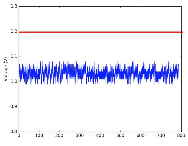
Figure 2.2 : DC Voltage Readings on TI MSP430G2 (blue) and Threshold (red)
As seen in Figure 2.2, the noise is within reasonable bounds of 100 mV because of the higher resolution ADC as well as defining a moving average voltage read in the microcontroller code. By feeding the EXP430G2 with a DC voltage from the AD8318, we were able to choose a voltage range, such as 1.45 Volts to 1.49 Volts, and use this range to indicate RF reception. If the DC output is within this programmed voltage range, the endpoints indicate reception by driving an LED.
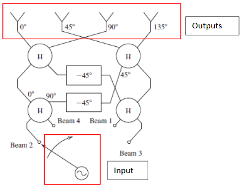
Figure 2.3 : Functional Diagram, Four Beam Butler Matrix Beamformer, Port 1 Excitation
The Butler matrix utilizes a number of design elements in order to achieve the phase difference desired at the output. The four elements are the 45 degree phase shifter, 90 degree phase shifter, quadrature hybrid coupler, and 4 port crossover. These elements are implemented using microstrip technology, which consists of transmission lines created by copper strips separated from the ground plane by a PCB substrate layer. The entire design is prepared using a combination of Agilent ADS schematic simulation in conjunction with CST far field and other 3D simulation. Select simulation substrate parameters are shown in the table below for the chosen material of FR – 4 and design frequency of 5.8 GHz.
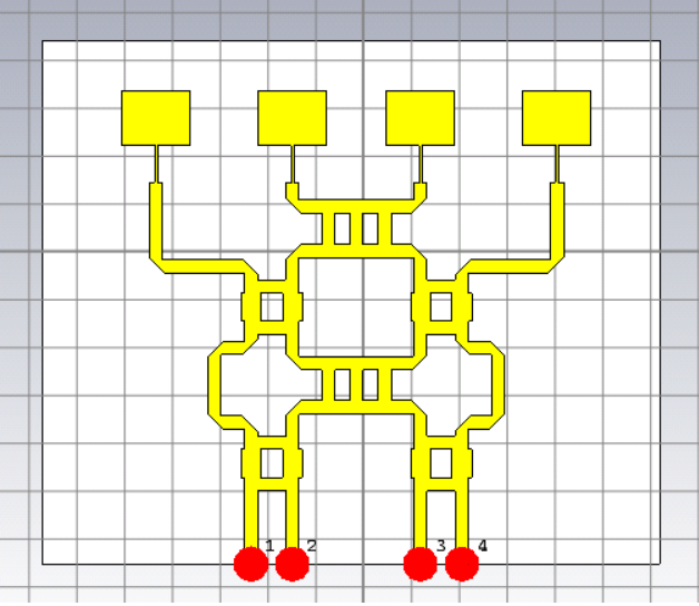
Figure 2.15 : Combined Butler Matrix and Patch Array
The patch antennas and Butler matrix as designed were imported into CST for 3D RF simulation. The combined patch and Butler matrix array is shown in Figure 2.15.
FABRICATION PROCESS
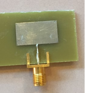
Figure 3.1: Patch Antenna as Manufactured
In choosing a manufacturing partner for these PCBs, one of the important aspects that should be considered is the RF properties of the substrates used. If the fabrication partner uses FR – 4 substrate with slightly different dielectric properties than as simulated, it becomes necessary to manually tune the end product. An example of this is shown in the design and fabrication of the single element patch antenna, which required an increase in the patch length from 10 mm to 10.9 mm. The patch width, feed width, and feed length are kept the same. As simulated with a patch length of 10 mm, the patch antenna shows good resonance at 5.8 GHz. The antenna as manufactured however showed resonance at 6.2 GHz in Figure 3.1.
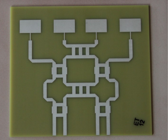
Figure 3.5: Butler Matrix Fed Phased Array, as Manufactured
For the Butler matrix fed antenna array, a board manufacturer with more precise specifications for the substrate used as well as tighter manufacturing tolerances was selected. This resulted in the board as shown in Figure 3.5.
TEST SETUP, MEASUREMENTS, AND RESULTS
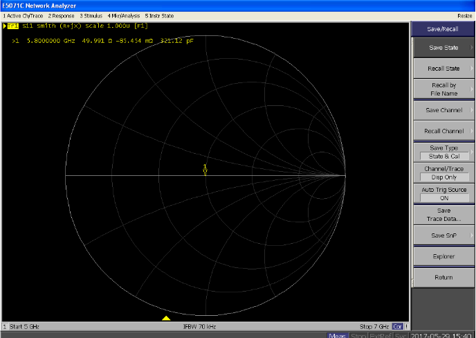
Fig 4.1 : Smith Chart of S11 After VNA Calibration at 5.8 GHz, 50 Ω Load
The VNA measurements were carried out first by performing standard short, open load calibration of the VNA in the frequency range of 5 to 7 GHz. When taking measurements, ports not under test are terminated using 50 ohm loads. Each port’s S – parameters are taken individually. This yields measurements for S11, S22, S33, and S44.
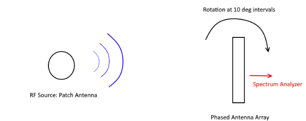
Figure 4.6 : Radiation Pattern Test Setup
The test setup for radiation pattern measurement was created using two ME1300 Dreamcatcher Antenna Training Kits, utilizing the metal poles as towers while bypassing the internal circuitry. A diagram of this set up is shown in Figure 4.6. The roundabout methods are necessary because the ME1300 kits are not rated for use at 5.8 GHz – using this setup, the internal circuitry of the ME1300s are bypassed.
SUSTAINABILITY AND ENVIRONMENTAL IMPACT
The foundation of Anthrolink is rooted in ethical intent and addressing overarching global challenges. Over the course of product development, we have shifted emphasis from solely phased antenna arrays to a comprehensive system validation. Our goals include creating a cost – effective system that is energy efficient while providing resilient networking abilities to the individual. While a proof of concept system in 5G beam steering technology has many industrial solutions, our primary intended end users are individuals who lack access to the Internet.
- Environmental & Energy Considerations
- Materials Consideration
- Social Impact
- Health
- Operation
CONCLUSION
Anthrolink presents a prototype system that illustrates how a next generation 5G communication system might behave and operate. To this end, electrical beamforming is utilized to provide an energy efficient method of steering signals to and from various endpoints. Domain knowledge acquired in previous electromagnetics coursework such as ELEN 144, RF and Microwave Components, is used to design and fabricate the antennas that are central to electrical beamforming and transmission of signals. System design knowledge gained in Power Electronics, ELEN 164, is used as background for the selection of appropriate system components for RF to DC conversion.
The implementation of endpoints using microcont rollers demonstrates potential further work in developing an interconnected content – aware local area network that has the ability to adjust its properties based on network conditions. In addition, these endpoints underscore the importance of data collection and utilization of data as a means of determining priority. The notion of content aware switching is important in a society where decisions are underpinned by the analysis and collection of vast amounts of data.
Additional work will involve further automation of the involved components as well as streamlining our design for mass production. In effect, this would mean replacing more of our custom build components with ready made parts. This would have the advantage of reducing volatility and batch difference between run of PCBs, antennas, and other materials. Furthermore, a reliance on ready made parts shifts some of the burden of part validation and testing to the manufacturer of the part in question.
Further improvements can also be made on the design of the phased antenna array itself. Using other substrates than FR – 4, such as RO3006 or RO4350B, would allow further improvement in the optimization process. The design of an improved array would greatly increase the delivered signal to each endpoint while keeping footprint the same. Similar improvements can be made to the feed network – for instance, a variable phase would allow for corrections in phase errors introduced during the design or manufacturing process as well as adding the capability to alter the shape and direction of transmitted beams.
Source: Santa Clara University
Authors: Jonathan Lee | Srinivaas Sekaran
>> Top IoT Projects using Microcontroller for Engineering Students
>> 60+ Antenna Communication Projects for Engineering Students
>> Final Year Project on Microstrip Antenna for Engineering Students
>> 200+ IoT Led Projects for Final Year Students
>> IoT based Networking Projects for Engineering Students