ABSTRACT
Vehicular antenna systems for jamming and communications are frequently mounted on either the roof or rear bumper of the vehicle. While this facilitates easier mounting and maintenance of the antenna systems, it reduces the maneuverability and increases the visual profile of the vehicle. This thesis researches alternative mounting locations such as underneath the vehicle or on the sides of the vehicle.
For either mounting location, the presence of the ground electrically close to the antenna system may drastically modify its performance and characteristics. Therefore, it is vital to understand how the presence of the ground affects the antenna’s patterns, impedance, efficiency, and axial ratio when the antennas are designed to be circularly polarized.
Once the effects of the grounds on the antenna systems are understood, steps can be taken to mitigate potential adverse effects and capitalize on any benefits. To better understand propagation close to the ground, both with and without the vehicle model, ideal sources were initially studied. More conductive soils offer higher efficiencies, but cause a greater amount of depolarization for circularly polarized sources.
For sources under the vehicle, the source is not just having a stronger coupling with the ground, but the vehicle body redirects energy back towards the ground. To mitigate this, the parallel plate source is proposed for HF and VHF frequencies. Small modifications to the geometry can achieve significantly higher efficiencies for sources under the vehicle. Other antennas are considered for operation in the UHF region.
For antenna systems mounted on the side of the vehicle, two mounting approaches (for spiral antennas) are considered. First, a cavity-backed aperture is mounted flush with the vehicle’s body. The second configuration has the spiral antenna aperture offset from the vehicle thus requiring minimum changes to the vehicle’s body. While the first approach is more commonly used, the latter provides greater gain and efficiency at the lower end and comparable gain and efficiency at higher frequencies while maintaining good axial ratio.
For side mounted sources, the four arm spiral provides a lower and more stable axial ratio when compared to the two arm spiral. Both antennas offer similar efficiency, but the four arm spiral maintains higher quality performance with the introduction of a cavity backing. The performance of side mounted sources can be further improved with the use of the spiral-helix that improves both the low and high frequency performance.
COMPUTATIONAL ELECTROMAGNETICS: SOLVERS AND MODELING
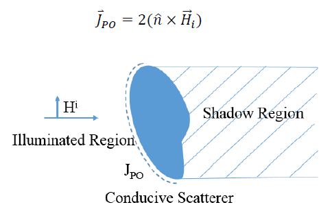
Figure 2.2. Incident field on a conductive scatterer producing both an illuminated and shadowed region. The surface current is nonzero in the illuminated region.
Because the energy only flows along these rays, rays that are incident on a scattering surface will necessarily create illuminated and shadowed regions (Figure 2.2). Physical Optics considers each point on the illumination region of the scatterer as if it was scattering off an infinite plane tangent to that point. In the shadowed regions, the incident field is considered to be zero.
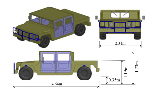
Figure 2.5. Dimensions of the complex Humvee model. The vehicle body is modeled as PEC with rubber wheels with a εr of 3 and conductivity of 10-15S/m.
The complex Humvee model dimensions can be seen in Figure 2.5. The body of the vehicle is PEC with rubber wheels with a relative permittivity of 3 and conductivity of 10-15S/m. The model contains a variety of features such as doors, mirrors, and front grill. All of these features require fine meshing to properly model and thus increase the required memory and computation time. The inclusion of the dielectric wheels even further increases the computational cost.
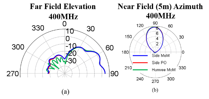
Figure 2.9. Comparison of the three models. (a) Comparison of azimuthal near field at 5m and (b) far field elevation patterns in the yz plane so that 90 degress corresponds to the boresight direction.
As can be seen in Figure 2.9, all three models have very good agreement for the near field electric field in the azimuth. The main lobes of each models also have very good agreement. The only location with poor agreement is the back lobes for the reduced rough Humvee model for both method of moments and physical optics. This results in a loss of detail to the backlobes. However, for higher frequency studies, the backlobes are less of a concern and such models are acceptable for these studies.
CHARACTERIZATION OF FIELDS FROM IDEAL SOURCES
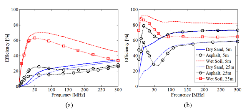
Figure 3.1. Efficiencies for the VED at both (a.) 0.3m and (b.) 1.78m above various grounds for different radii.
For the first case, the vertical electric dipole is placed at either 0.3m or 1.78m above one of the following, dry sand, asphalt, or wet soil. The source radiates between 3MHz and 300MHz. This study is primarily concerned with the near field performances of the sources and will compute the efficiencies from 5m and 25m radius hemispherical shells. The efficiencies for both heights and distances can be found in Figure 3.1.
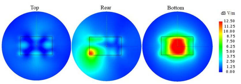
Figure 3.6. Electric field strength 10cm above dry sand for under the vehicle model at 100MHz for each mounting position.
This study in interested in finding a source with strong, uniform fields around the vehicle body. The electric field strength was computed 0.1m above the ground directly under the vehicle and up to 5m away from its center. All three mounting positions were considered over the dry sand ground at 100MHz. While the top position offers uniform fields, the bottom position has greater field strength while maintaining good field uniformity (Figure 3.6).
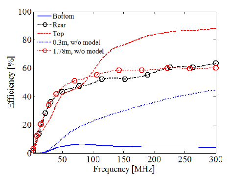
Figure 3.12. Efficiency of the crossed electric dipoles for the three antenna positions over dry sand with and without the vehicle model.
As seen in Figure 3.12, the low efficiency for the bottom position holds true for the crossed electric dipoles as well. Increasing the efficiency will be the most important part of improving the utility of the bottom as a mounting location.
ANTENNA MOUNTING ON THE VEHICLE BOTTOM
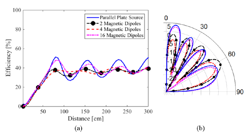
Figure 4.5 Comparison of parallel discs source 0.3m above dry sand and 2,4, and 16 horizontal Hertzian magnetic dipoles to approximate a ring of magnetic current for efficiency (a) and elevation cut at 300MHz (b).
When the number of horizontal magnetic dipoles is 16, there is a good agreement with parallel plate results in efficiency (Figure 4.5). While the model of a constant magnetic current loop does compare well with the parallel discs, there are some discrepancies in the computed performances. This is due to the fixed height of the parallel discs resulting in a magnetic current loop that is 10 cm tall.
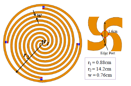
Figure 4.23. Geometry of the mode-2 four-arm spiral antenna and close up of feed that will be used under the vehicle.
To evaluate the effects of ground proximity and viability of mounting a spiral antenna on the bottom of a vehicle, the mode-2 four-arm spiral antenna with a 25.4 cm diameter was selected to be used. The configuration is a self-complementary Archimedean spiral with the layout shown in Figure 4.23.
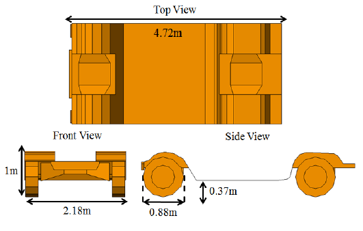
Figure 4.32. Model of the vehicle bottom with PEC wheels.
For reference calculations, the bottom vehicle profile is modeled as shown in Figure 4.32. This model includes some details of the vehicle geometry around the wheels and axles of the vehicle since their size is comparable to the wavelengths of interest. The PEC wheels are also included in the model.
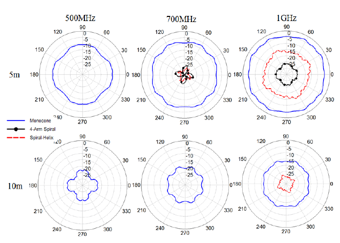
Figure 4.39. Azimuthal electric near field patterns in dB.
Figure 4.39. Azimuthal electric near field patterns in dB 5m and 10m from the source and 0.32m above the dry sand ground under the 2m x 2m PEC plate. There is low variability for the modified monocone source compared to the other sources. The modified monocone source also has a much stronger electric field near the source.
SIDE MOUNTING OF SPIRAL ANTENNAS
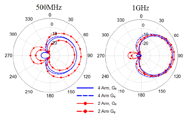
Figure 5.15. Theta and phi polarizations of the far field gain patterns of the two and four arm spirals in free space. The four arm spiral patterns are the same at boresight and corresponds to its lower axial ratio.
This is also observed in the far-field patterns of the two and four arm spirals in free space (Figure 5.15). The two-arm spiral has a greater amount of pattern rotation that is observed as the theta and phi polarizations change dominance as the frequency changes. This correlates with its poorer axial ratio performance compared to the four-arm spiral.
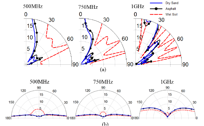
Figure 5.22. Elevation (a) and azimuthal (b) cuts of the axial ratio of the four arm spiral over dry sand, asphalt, and wet soil. The elevation cuts are along the boresight axis while the azimuthal cuts are from 5 degrees above the ground.
As expected, axial ratio deteriorates further from the boresight (Figure 5.22). The more conductive grounds have smaller angle with small axial ratio. Generally, the axial ratios are low up to about 15 degrees above the ground. As the frequency increases, the region of small axial ratio decreases from about 25 degrees at 500MHz to about 15 degrees at 1GHz.
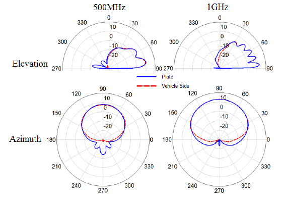
Figure 5.28 Elevation and azimuth cuts of the far field of both the vehicle side and plate geometries over the dry sand ground. There is good agreement between the two with discrepancies in the backlobes.
The reductions to the model are verified that they maintain good agreement with the previous models (Figure 5.28). Both the elevation and azimuthal patterns of the two geometries have very good agreement. There are discrepancies between the two geometries’ backlobes. This is acceptable for this study, as it is concerned with the use of these antennas as sectorial sources.
SUMMARY, CONCLUSIONS AND FUTURE RESEARCH
Summary and Conclusions
As we move forward into the 21st century, the need for electronic warfare and electronic countermeasures is only increasing. Current antenna systems for such applications as well as for communication applications frequently use large antennas mounted on the roof or rear bumper of vehicles. While these can be attractive mounting locations for ease of mounting and their radiation propagation properties, they contribute to a large visual profile that can hinder the maneuverability and increase the vulnerability of the vehicle.
Chapter 2 considered the theoretical basis for the computational tools used to perform the studies found in this thesis; specifically, it discussed the method of moments, physical optics, and a hybridization of the method of moments with physical optics. As well, the ground and vehicle models used in this thesis were discussed.
Future Research
There are three main avenues for future work and research: layered ground models, optimization of the parallel plate source, and alternate ultra wideband sources for sectorial use. This thesis considered three different uniform grounds. To better understand the effects of grounds on propagation and antenna performance, layered ground types could be explored. These layered ground types could be as simple as combining the already used ground parameters, such as asphalt of variable thicknesses over dry sand or wet soil.
The addition of the fins to the parallel plate source greatly improved its performance. If such small modifications to the geometry can yield improved performance, there is still a lot of potential for even further improvements. The current method of exciting the antenna yields a narrow bandwidth. Exploring potential modifications to improve the efficiency and bandwidth of the antenna would move it forward from a concept to a potential reality. As well, a tuning circuit could be designed and implemented to improve its performance and allow operation across a wider range of frequencies, even if they cannot all be covered simultaneously.
Source: University of Colorado
Authors: Timothy W. Samson
>> 60+ Antenna Communication Projects for Engineering Students
>> Projects on Antenna and Wave Propagation for Final Year Students