ABSTRACT
Harmonic distortion in power networks has greatly reduced power quality and this affects system stability. In order to mitigate this power quality issue, the shunt active power filter (SAPF) has been widely applied and it is proven to be the best solution to current harmonics. This paper evaluates the performance of the modified synchronous reference frame extraction (MSRF) algorithm with fuzzy logic controller (FLC) based current control pulse width modulation (PWM) inverter of three-phase three-wire SAPF to mitigate current harmonics.
The proposed FLC is designed with a reduced amount of membership functions (MFs) and rules, and thus significantly reduces the computational time and memory size. Modeling and simulations of SAPF are carried out using MATLAB/Simulink R2012a with the power system toolbox under steady-state condition, and this is followed with hardware implementation using a TMS320F28335 digital signal processor (DSP), Specrum Digital Inc., Stafford, TX, USA.
The results obtained demonstrate a good and satisfactory response to mitigate the harmonics in the system. The total harmonic distortion (THD) for the system has been reduced from 25.60% to 0.92% and 1.41% in the simulation study with and without FLC, respectively. Similarly for the experimental study, the SAPF can compensate for the three-phase load current by reducing THD to 5.07% and 7.4% with and without FLC, respectively.
PROPOSED SAPF
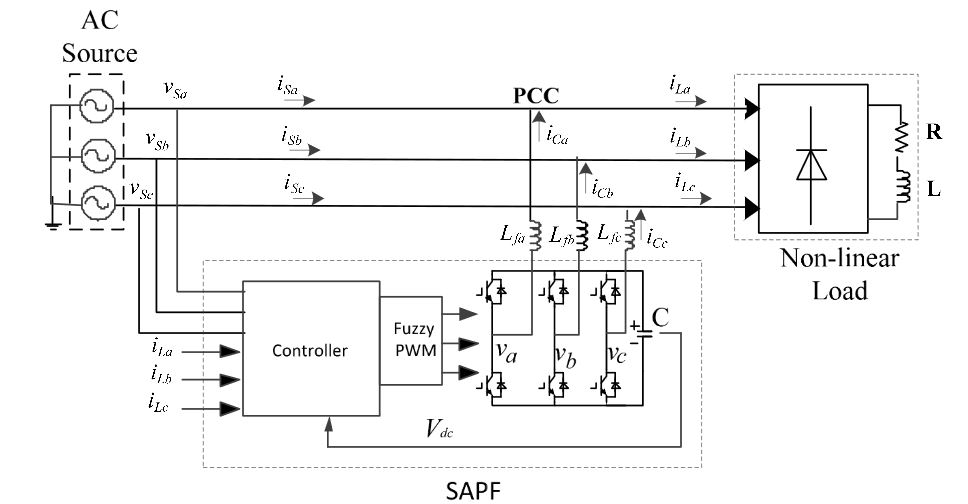
Figure 1. Block diagram of the three phase shunt active power filter
The proposed three-phase SAPF is connected at the point of common coupling (PCC) between the three-phase supply and the nonlinear load, as shown in Figure 1. The nonlinear load consists of a three-phase full bridge rectifier which is further connected to an inductive (RL) load. The SAPF operates by injecting compensation current into the utility via PCC to cancel out the current harmonics and at the same time drawing a small amount of current from the utility to regulate its switching losses.
CONTROL STRATEGIES
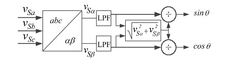
Figure 3. Block diagram of the unit vector generation
For generating the synchronization vector, a simple and efficient approach is adopted in calculating the output of the unit vector model in the MSRF method. Figure 3 shows the diagram of a unit vector generation.
FUZZY LOGIC CURRENT CONTROL
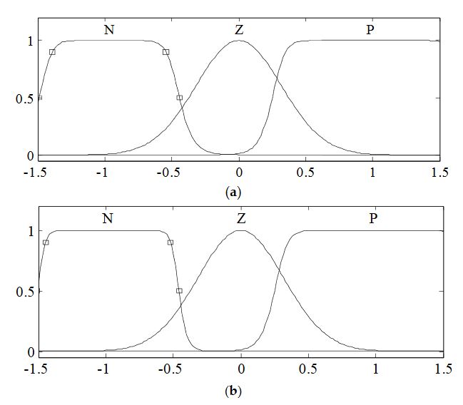
Figure 4. Inputs variables of fuzzy logic controller
This is known as fuzzification. Knowledge base comprises data and the rule base so as to coordinate with the other unit. Meanwhile, inference is developed based on this set of rules. Finally, the result is converted back into a specific control output value at the defuzzification stage. One advantage of fuzzy logic control is that it does not require any accurate mathematical model of a system. In this work, the FLC is designed with two inputs known as error and change in error (e and ce) and an output called actuatinsig. Figure 4 shows the diagram of the input variables while Figure 5 shows the output variable.
SIMULATION RESULTS
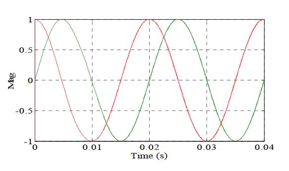
Figure 7. Sine and cosine function from the unit vector circuit
Figure 7 shows the output waveform of the unit vector synchronizer: the sine and cosine function needed for synchronization purposes and for the generation of reference current signals. It is clear that the sine and cosine functions are effectively generated, thus ensuring proper generation of the required reference current signals. Meanwhile, Figure 8 shows the source voltage and current waveforms before compensation.

Figure 11. Simulation result of SAPF which includes the three-phase source voltage
Next, Figure 11 shows the simulation waveform of SAPF which includes the source voltage after compensation vS, source current after compensation iS, compensation current, and DC bus capacitor voltage resulting from the SAPF utilizing the current control scheme with and without the FLC controller. From the results, it is clearly shown that the source current is now sinusoidal and in phase with the source voltage for both cases.
EXPERIMENTAL VERIFICATION
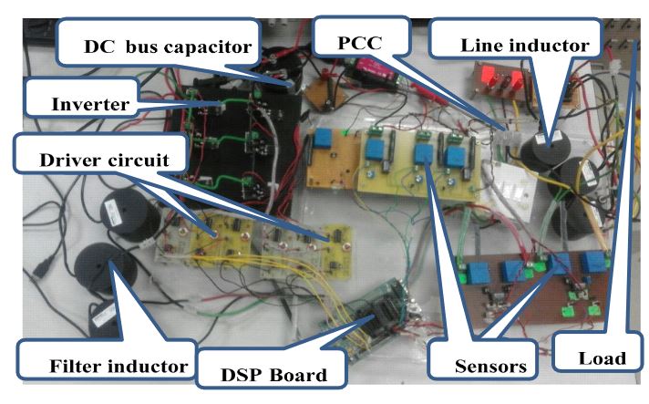
Figure 14. Picture of the hardware set up
The hardware set up consists of three main parts: the measurement circuit implemented with the Hall Effect current and voltage sensors, driver circuit, and the DSP-based control unit, as displayed in Figure 14. The measurement circuit converts the three-phase current/voltage into 0–3 V level signals which serve as inputs to the A/D (analog-to-digital) module of the control circuit.
CONCLUSIONS
This paper presents MSRF based SAPF with a current control scheme employing FLC to compensate for the current harmonics in the three-phase three-wire system using the MATLAB/Simulink platform and it is experimentally validated with DSP TMS320F28335. The control scheme is capable of suppressing the harmonics in the system in balanced sinusoidal conditions. The operating principle of the MSRF technique is similar to the conventional SRF method, and the main difference is that it consists of simplified unit vector generation instead of the conventional PLL circuit to produce the sine and cosine angles for synchronization purposes.
The technique is efficient with good performance capabilities. FLC is used to improve the performance of the PWM current controller. The designed FLC consists of a reduced amount of MFs which aims to reduce complexities and ease implementation. This decreases the tough tuning routines and implementation costs, making the system more efficient. The simulation results show the effectiveness of the control algorithms in mitigating the harmonics in the system by reducing the THD from 25.60% to 0.92% and 1.41% with and without FLC, respectively.
The experimental results also show that the three-phase SAPF utilizing these control strategies can compensate for the three-phase load current by reducing the THD to 5.07% and 7.4% with and without FLC, respectively. Furthermore, both the simulation and experimental findings have shown the effectiveness of the proposed current control scheme under transient-state conditions by achieving a response time of 0.02s.
Source: University Putra Malaysia
Authors: Suleiman Musa | Mohd Amran Mohd Radzi | Hashim Hizam | Noor Izzri Abdul Wahab | Yap Hoon | Muhammad Ammirrul Atiqi Mohd Zainuri
>> 200+ Matlab Projects for Control System for Final Year Students
>> More Matlab DSP Project Ideas for Engineering Students