ABSTRACT
Multi-terminal high voltage direct current transmission based on voltage source converter (VSC-HVDC) grids can connect non-synchronous alternating current (AC) grids to a hybrid alternating current and direct current (AC/DC) power system, which is one of the key technologies in the construction of smart grids. However, it is still a problem to control the converter to achieve the function of each AC system sharing the reserve capacity of the entire network.
This paper proposes an improved control strategy based on the slope control of the DC voltage and AC frequency (V–f slope control), in which the virtual inertia is introduced. This method can ensure that each AC sub-system shares the primary frequency control function.
Additionally, with the new control method, it is easy to apply the secondary frequency control method of traditional AC systems to AC/DC hybrid systems to achieve the steady control of the DC voltage and AC frequency of the whole system. Most importantly, the new control method is better than the traditional control method in terms of dynamic performance. In this paper, a new control method is proposed, and the simulation model has been established in Matlab/Simulink to verify the effectiveness of the proposed control method.
SYSTEM AND MODEL DESCRIPTION
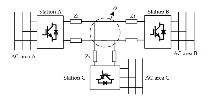
Figure 1. Structure of the multi-terminal DC grid
The research object of this paper adopts a bipolar-operation, three-terminal HVDC system with a star topology. The bipolar-operation, three-terminal HVDC system of this paper is a hypothetical power system. The DC-side uses a unified rated voltage of ± 200 kV. DC lines adopt lumped parameters. The line capacitance effect is focused on the DC-side of the converter and the line inductance is ignored. The structure of the power grid is shown in Figure 1.
PROPOSED CONTROL METHOD
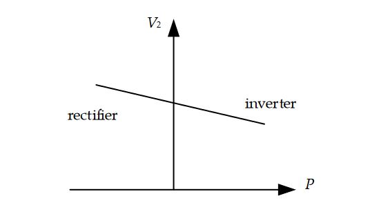
Figure 4. Operation characteristics of the transmission power and the DC-side voltage
As shown in Figures 4 and 5, if the converter station operates in the inverter state, when the frequency of the AC system decreases, the AC side hopes to obtain more active power to support its frequency; thus, it requires the terminal voltage of the DC-side to be decreased to satisfy a more active power transmission. When the frequency of the AC system increases, the AC-side hopes to obtain less active power and the terminal voltage of the DC-side should be increased.
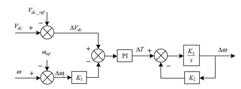
Figure 7. The control loop of the DC voltage and AC frequency
In addition, to make the converter automatically sense frequency fluctuations of the AC system and supply energy to AC grids,the converter should make the AC frequency as feedback in the outer control loop. The virtual inertia is introduced in the control strategy, which makes the converter achieve dynamic power sharing, as for the traditional synchronous generator when a load disturbance occurs in the AC system. Additionally, to ensure that the converter has the ability to support DC voltage, the converter should also make DC voltage a feedback in the outer control loop. The control loop is shown in Figure 7.
PARAMETER DESIGNS
The DC voltage and AC frequency slope coefficient K1 is a key parameter in the new control method. It has a similar design principle to the typical speed-droop characteristics of traditional power plants. With respect to the typical speed-droop characteristics of traditional power plants, it requires a load fluctuation ∆P within the range of ± 5%; the whole range of primary frequency control is released when the frequency error is about ± 200 mHz.
SIMULATION STUDY
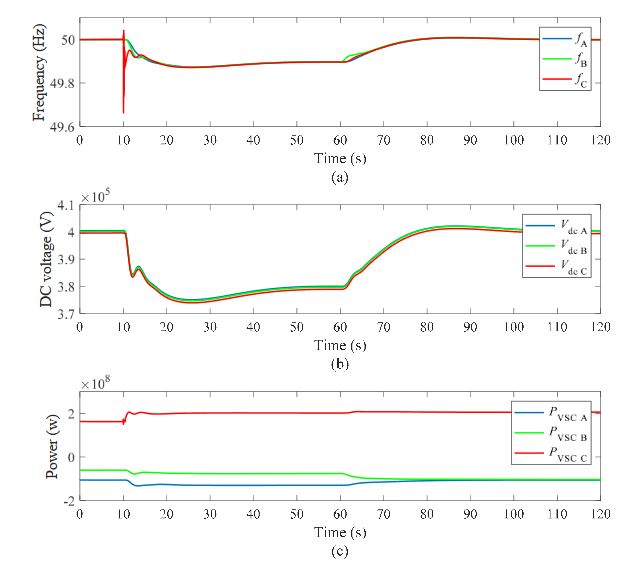
Figure 11. The waveforms of secondary frequency control
With the same simulation condition, the response of the traditional control method is shown in Figure 11. The waveforms of Figure 11 are similar to those of Figure 10, while the dynamic performance of Figure 11 is poor, as at t = 10 s and t = 60 s, the waveforms of Figure 11 have more fluctuation than for Figure 10. Thus, this proves that the new control method is better than the traditional control method in terms of dynamic performance.
CONCLUSIONS AND FUTURE WORK
For the power balance control of multi-terminal VSC-HVDC systems, this paper improves the traditional converter station control mode by adopting the DC voltage and AC frequency slope (positive correlation) control mode. The paper adds a virtual moment of inertia into the control strategy. The control method has two functions. First, it supports different asynchronous AC systems sharing their primary frequency control function.
Second, it is convenient for the AC/DC hybrid system to inherit the secondary frequency control methods of the traditional AC system. The simulation results prove that the new control method is better than the traditional control method in terms of dynamic performance. The new control method of the VSC-HVDC converter station has some potential value for further study. The frequency control strategy, grid-on and isolated island operation strategy and stability analysis will be researched in a follow-up study.
Source: Xian Jiaotong University
Authors: Hao Wang | Yue Wang | Guozhao Duan | Weihao Hu | Wenti Wang | Zhe Chen
>> 200+ Matlab Projects for Control System for Final Year Students