ABSTRACT
The evolving multiphase induction generators (MPIGs) with more than three phases are receiving prominence in high power generation systems. This paper aims at the development of a comprehensive model of the wind turbine driven seven-phase induction generator (7PIG) along with the necessary power electronic converters and the controller for grid interface. The dynamic model of the system is developed in MATLAB/Simulink (R2015b, The MathWorks, Inc., Natick, MA, USA). A synchronous reference frame phase-locked loop (SRFPLL) system is incorporated for grid synchronization.
The modeling aspects are detailed and the system response is observed for various wind velocities. The effectiveness of the seven phase induction generator is demonstrated with the fault tolerant capability and high output power with reduced phase current when compared to the conventional 3-phase wind generation scheme. The response of the PLL is analyzed and the results are presented.
PROPOSED SYSTEM DESCRIPTION
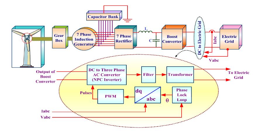
Figure 1. Seven Phase Grid Connected Wind Electric Generator
Figure 1 shows the proposed multiphase AC power system for wind power application. The grid connected seven phase wind generation system considered for the study, consists of a wind turbines that is driven by a 7PIG through a gearbox. The generated seven phase AC output is rectified by the seven phase rectifier and filtered by an LC filter. The filtered and boosted DC output voltage is injected through a three phase inverter to the grid with proper synchronization through SRF PLL. The inverter is controlled using the synchronous d-q reference frame approach.
MODELING OF SYSTEM COMPONENTS
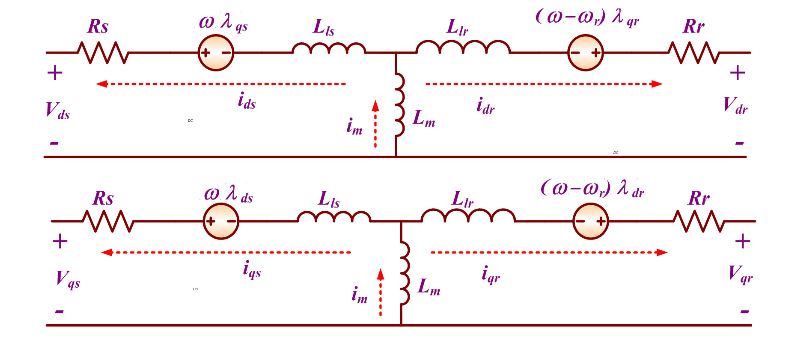
Figure 2. d-q -axis Equivalent Circuit of Seven-Phase Induction Generator (7PIG)
The mathematical modeling of the seven phase wind generator components, namely the wind turbine, seven phase induction generator, seven phase rectifier, and three phase inverter and PLL are discussed in the following sections.
DC LINK CONVERTER
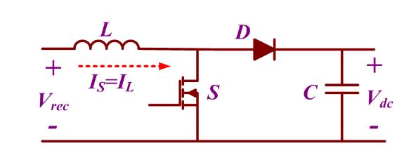
Figure 3. Power Circuit of Boost Converter
The power electronics based interface system, namely the DC link converter, involves a seven phase rectifier, three phase inverter, and a DC-DC boost converter. The uncontrolled seven phase rectifier converts the seven phase AC output of the generator to DC and is boosted by the boost converter.
GRID INTERFACE USING PLL
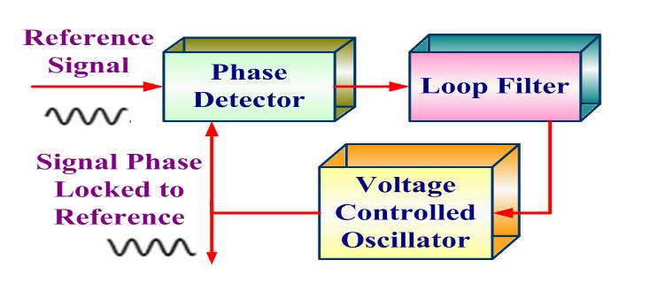
Figure 4. Basic Phase Locked Loop (PLL) Structure
The effective power transfer between the grid and the source can be realized by the efficient synchronization technique. The most familiar method is tracking of the phase angle using the PLL which synchronizes the voltage and frequency of a given reference and output signal. A phase detector, loop filter, and voltage controlled oscillator (VCO) together make a basic PLL system, wherein the phase detector generates an error signal by comparing the reference and output signal. The harmonics of the error signal are eliminated by the loop filter. Depending on the output of the loop filter, the VCO generates the output signal. Th e basic structure of the PLL circuit is shown in Figure 4.
SIMULATION RESULT
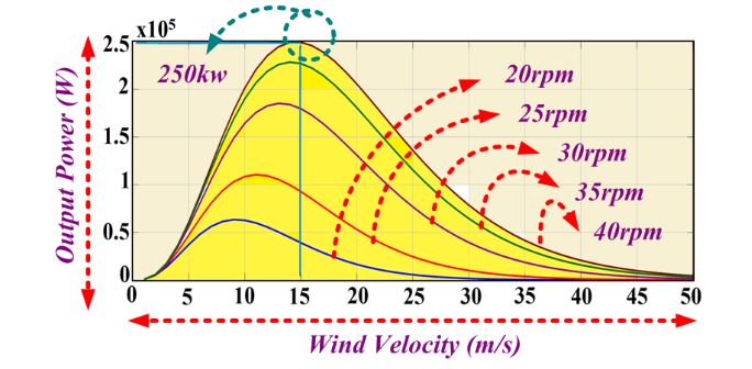
Figure 6. Wind Turbine Power Output vs. Wind Velocity (Wind Speed)
A 250 kW wind turbine is simulated using the Equations (1)–(4) for various wind speeds and rotational speeds. Figure 6 shows the power curves of the wind turbine at various wind speeds. The rated power of 250 kW is achieved at the rated wind speed of 15 m/s and 40 rpm. The wind turbine produces the maximum power at various rotational speeds for the different wind speeds.
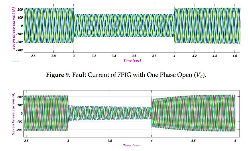
Figure 10. Fault Current of 7PIG with Two Phases Open
The most important ability of the multiphase phase generator is that it continues to operate even after the fault occur in one (or more) phase(s), whereas three-phase machines can hardly continue their operation. Under the faulty conditions, the additional degrees of freedom available in MPIG are efficiently used for the post fault operating strategy.
One, two-phases are open circuited Vc, Vc and Vd at t = 3 s for the seven phase induction generator for the investigation test. It is clear from the obtained numerical results by Figures 9 and 10 that the generator continues to operate with the reduced phase current in amplitude for continuous propagation under open circuit faulty conditions.
CONCLUSIONS
In this article, a comprehensive model of a wind driven 7PIG in grid connected mode was developed using the two axis d-q equivalent circuit. A seven phase wind electric generator is integrated using the individual system components and the performance of the seven phase wind electric generator is analyzed for varying wind speed. A synchronous reference frame PLL incorporated for the grid interface is simulated and analyzed. The enhanced performance of 7PIG is evaluated through the fault tolerant capability and high output power with reduced current per phase when compared with the three phase model.
The performance of SRF-PLL incorporated in the grid connected seven phase wind electric generator was analyzed for various operating grid conditions. The use of multiphase machines along with the PLL synchronization of the grid increases the reliability of the WEG. Notably by the possibility of achieving post-fault disturbance free operation provided by the seven phase machine, as well as the constant voltage and frequency operation enabled by the d-q PLL.
Source: University of Johannesburg
Authors: Kalaivani Chandramohan | Sanjeevikumar Padmanaban | Rajambal Kalyanasundaram | Mahajan Sagar Bhaskar | Lucian Mihet-Popa
>> 80+ Matlab Projects based on Power Electronics for Engineering Students