ABSTRACT
This paper introduces a sliding mode control (SMC)-based equivalent control method to a novel high output gain Cuk converter. An additional inductor and capacitor improves the efficiency and output gain of the classical Cuk converter. Classical proportional integral (PI) controllers are widely used in direct current to direct current (DC-DC) converters. However, it is a very challenging task to design a single PI controller operating in different loads and disturbances.
An SMC-based equivalent control method which achieves a robust operation in a wide operation range is also proposed. Switching frequency is kept constant in appropriate intervals at different loading and disturbance conditions by implementing a dynamic hysteresis control method. Numerical simulations conducted in MATLAB/Simulink confirm the accuracy of analysis of high output gain modified Cuk converter. In addition, the proposed equivalent control method is validated in different perturbations to demonstrate robust operation in wide operation range.
HIGH OUTPUT GAIN MODIFIED CUK CONVERTER
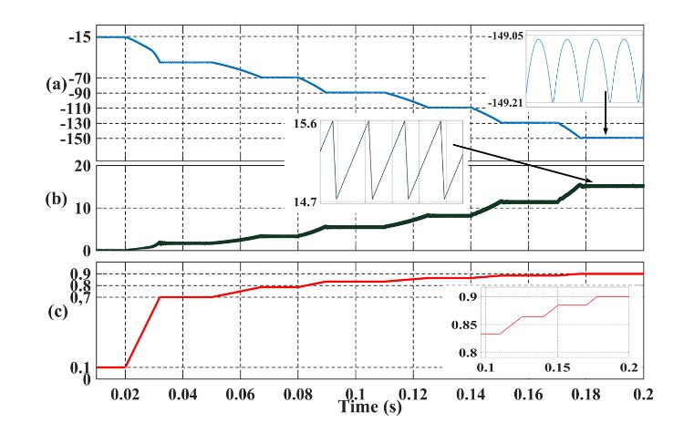
Figure 3. Simulation of modified cuk converter. (a) Output voltage (b) Input Current (A) (c) δ
Different δ values are applied in the simulation, as shown in Figure 3c. Output voltage (Vo) and input current (ii) curves change accordingly, as shown in Figure 3a,b, respectively. Output voltage and input currents are zoomed; it is observed in simulations that the frequency of the ripples is equal to the SF (150 kHz).
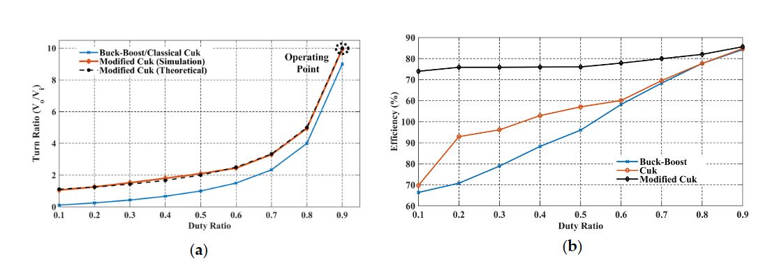
Figure 4. Comparison of buck/boost, Cuk, and modified Cuk converter. (a) Duty Ratio; (b) Efficiency
The performance of the modified Cuk converter was compared to classical Cuk and buck/boost converter circuits. Figure 4a shows δ comparison of converters. A simulation platform is constructed in MATLAB/Simulink with the same parameters given in Table 1. Theoretical and simulation values of the modified Cuk converter validate the results. Efficiency comparison of simulated buck/boost, Cuk, and modified Cuk converter is depicted in Figure 4b. Modified Cuk converter efficiency is higher than classical Cuk and buck/boost converter.
EQUIVALENT CONTROL OF MODIFIED CUK CONVERTER
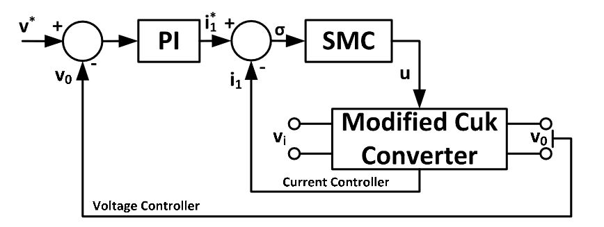
Figure 5. Cascaded control of modified Cuk converter. PI: proportional integral; SMC: sliding mode controller
A cascaded PI+SMC controller structure could be used for ease of implementation to modified Cuk converter as depicted in Figure 5. A simple external voltage controller can generate input current reference, while equivalent controller controls the input current.
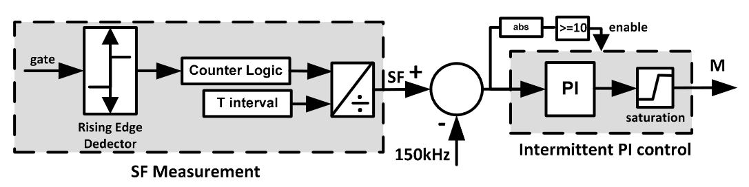
Figure 8. Switching frequency (SF) measurement and intermittent PI controller
Another drawback of the method is the requirement of the SF measurement. A SF measurement algorithm could be implemented by counting the rising edge of the gate signals at certain instants. If the number of rising signals is divided into a predefined time interval, SF can be easily calculated. As a result, an intermittent PI controller structure can keep the SF constant at a specified interval as shown in Figure 8. The output of the intermittent PI controller is the resultant M value of the dynamic relay with hysteresis function.
SIMULATION RESULTS
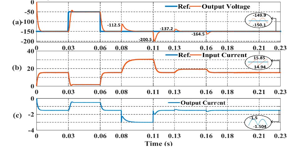
Figure 9. Performance of proposed equivalent controller. (a) Output Voltage (V); (b) Input Current (A); (c) Output Current (A)
Figure 9 shows the output voltage and input current response at different perturbations. Required trajectories are successfully tracked at all disturbances. Figure 9a shows the output voltage trajectory at all peak values at the instants of perturbations. The controller successfully passed all perturbations. Figure 9b,c shows the input and output currents of the converter.
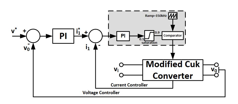
Figure 12. Comparison controller structure
A comparison between classical linear control methods and the proposed equivalent controller was also attempted to show the effectiveness of proposed method. A cascaded controller structure which consists of voltage and current PI controllers is depicted in Figure 12. In particular, some studies use single voltage PI controllers to control a DC-DC converter. However, this type of controller has a very limited operational range, and comparison of a single PI controller would be inconsistent due to the cascaded controller structure of the proposed equivalent controller.
CONCLUSIONS
This paper proposed a modified high output gain Cuk converter with an SMC-based equivalent controller. The efficiency and performance of a classical Cuk converter was improved by the simple inclusion of a single inductor and capacitor. Moreover, a constant switching frequency cascaded equivalent controller structure is proposed. Simulation results show the effectiveness and robustness of the proposed method, and the constant switching frequency approach to the SMC-based controller provides the opportunity of simple application to real systems.
Source: University of Johannesburg
Authors: Sanjeevikumar Padmanaban | Emre Ozsoy | Viliam Fedak | Frede Blaabjerg
>> 200+ Matlab Projects for Control System for Final Year Students