ABSTRACT
Nowadays, mobile systems can be used as a video stream transmitter as well as receiver. That is, mobile systems can send a movie with high resolution as a transmitter and a TV or monitor can display the movie on the fly as a receiver. Wireless video transmission technology suitable for mobile systems is divided into two parts: wireless communication technology and video coding technology. The most critical issue of the existing wireless video transmission technology for mobile applications is power consumption. But mobile devices have limited power source to meet high demand of power consumption. Practical solution is to reduce power consumption by wireless video transmission module in mobile devices.
The objective of the thesis is to design a new wireless video transmission technology as an alternative to the existing system that consists of popular standards IEEE 802.11 WLAN and H.264/MPEG. The proposed system will consume lower power an d be of small size for mobile device while achieving high resolution video. We achieve the objective by using two approaches. The first is to reduce size and power of each module independently. The second is to combine video coder with wireless transceiver for efficient streaming of video from mobile to large displays. As a key technology for wireless communication, we selected features of the IEEE WPAN standards 802.15.3c utilizing 60 GHz single carrier modulation.
It can support high resolution video with low power. As a video coding technology, we applied 3D-DCT (three-dimensional Discrete Cosine Transform). 3D-DCT takes very small area and less number of operations compared with H.264. Hence, it is expected to take low power as a single chip solution. These wireless communication and video coding modules are implemented efficiently in terms of hardware area and power. To implement the algorithms selected for the proposed system, proper specific VLSI architectures are selected or newly devised. In addition, both systems are combined together to reduce size and power and increase efficiency for a single chip solution.
3D-DCT VIDEO CODING
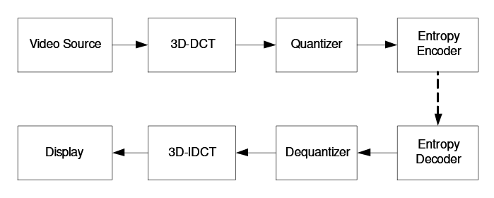
Figure 2.1: Dataflow of the 3D-DCT/IDCT video code
In this section, we review 3D-DCT and related algorithms. The block scheme of 3D-DCT is presented in Figure 2.1. Different from H.264, it does not have a loop for intra/inter prediction. In Figure 2.1, Quantization/Dequantization blocks include scaling/rescaling and quantization/dequantization. And, entropy encoder/decoder include scan ordering/deordering as well as entropy encoder/decoder.
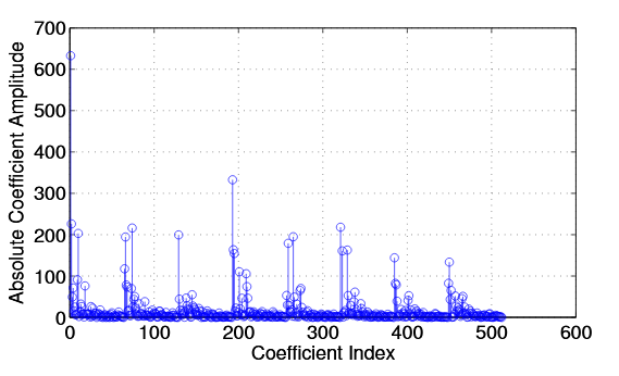
Figure 2.2: Distribution of 8 × 8 × 8 3D-DCT coefficients for Foreman QCIF frames 1-8
Figure 2.2 shows a plot of the coefficient values versus the coefficient numbers for some frames in a standard video sequence. The number is defined by P × 64 + M × 8 + N for a 8 × 8 × 8 cube. As shown, very similar patterns are repeated per each frame. The highest peak at position 0 corresponds to (M, N, P) = (0, 0, 0) which is DC component at the first frame where P is 0. Besides, the second high peaks correspond to (0, 0, P), DC components at the other frames where P is 1 to 7. The period of the second peaks is 64, M × N. The period of the third small peaks is 8 even though the amplitude of each coefficient does not decrease monotonically.
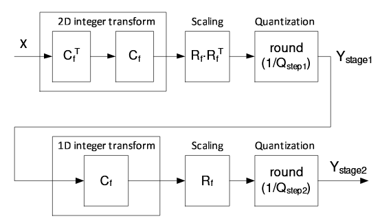
Figure 2.3: Forward transform and quantization process
Thus, we separate all processings for 2D-DCT from those for 1D-DCT as shown in Fig. 2.3. Cf and Rf are defined in section??. That is, transform, quantization, and scaling of 2D-DCT are completed at first stage. Then, output from the first stage go to the next transform, scaling, and quantization of 1D-DCT.
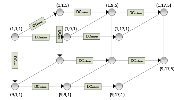
Figure 2.7: Registers and reference pixels for three direct ional DPCM for 8 × 8 × 4 3D-DCT
A good prediction of the 1st DC-component of a cube could be obtained from a combination of the 1st DC-components of all its neighboring cubes. Different from Sang et al. that considers only the previous cube to the left as a predictor, our encoder considers all its neighboring cubes to obtain a good prediction of the 1st DC-components. Our encoder needs only three registers DC frame, DC row, and DC column not to encode any DC absolute intensity as shown in Figure 2.7.
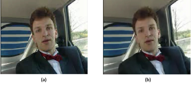
Figure 2.19: (a): Decoded frame, (b): Decoded and postprocessed frame
Figure 2.19-(a) shows an encoded and decoded result of the 1st frame in Carphone QCIF with QP 135. As shown, ringing and blocking artifacts are found which are typical artifacts that can be generated in 2D-DCT. They come out to spatial domain through 1D- IDCT, dequantization, and then 2D-IDCT. That is, artifacts on temporal domain are transformed to spatial domain. To get rid of those artifacts, we use a customized deblocking filter on spatial domain. Different from H.264, it is not in-loop filter but a postprocessing filter. Figure 2.19-(b) shows denoised result. As shown, critical artifacts are removed and PSNR is a bit increased. Of course, there is a trade-off between blurness and sharpness.
60 GHZ SINGLE CARRIER WIRELESS TRANSCEIVER
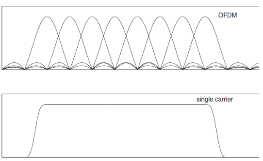
Figure 3.1: Frequency domain illustration of OFDM and SC systems
Orthogonal Frequency Division Multiplexing (OFDM) is the preferred modulation technique in many recent broadband wireless systems, because it allows relatively simple receivers in fading environments. Recently, Single Carrier (SC) techniques using Frequency Domain Equalization (SC-FDE), offering similar advantages, have also received a lot of attention. They can potentially alleviate the high back-off requirements of OFDM modulation, and thus enable significant cost and power savings. This paper compares both systems, in the context of Gbit/s radios at mm-wave (60GHz specifically).
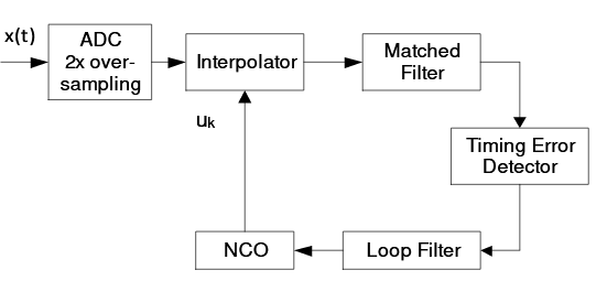
Figure 3.7: Baseline structure
Figure 3.7 shows the structure of original timing error recovery loop [?]. ADC samples received signals by using 2x clock. So, this recovery loop runs at 2x clock. At this time, main problem of 2x clock is timing. That is, if 2x clock is set as a system clock, it may cause lots of timing violations. Besides, it takes more power compared with 1x clock. Solution is to run on 1x clock as system clock.
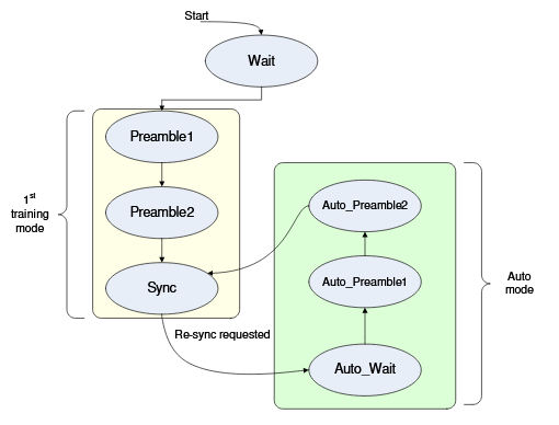
Figure 3.14: State diagram of proposed AGC and time synchronization algorithm
Figures 3.14 are block diagram and state diagram of proposed AGC combined with time synchronization algorithm. After reset (start signal), system waits for any signal at Wait state. At that state, threshold is set to 256 which is very small. Once 1st preamble sequence is detected, state goes to Preamble1 where maximum value among cross-correlation outputs is stored onto peak1 register.
When 2nd preamble sequence is detected, state goes to Preamble2 where the value of peak1 register is stored onto Max-peak register. Preamble2 state turns on automatic threshold mode where Max-peak /8 or Max-peak /16 is obtained using simple shift operation and updated every preamble sequence. Once sixteen peaks which correspond to sixteen 128 Golay sequences are detected, state moves to Sync state. At Sync state, AGC is also locked together.
INTEGRATION OF 3D-DCT VIDEO CODEC WITH 60 GHZ WIRELESS TRANSCEIVER
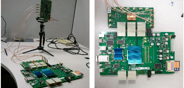
Figure 4.1: Indoor testbed setup
The final FPGA bistreams were downloaded to two FPGA boards. Figure 4.1 shows testbed setup by connecting all boards. HDMI input video stream came from a DVD player or playstation. Final HDMI output from the receiver side was going to a LCD moniter. High resolution (up to 1080p video) was played successfully without any noise by comparing input pixels to output pixels in office. Our whole system is strong against moving transmitter or receiver dynamically which is compensated by our proposed AGC.
CONCLUSION
We designed a wireless video transmission system. Our contribution is new algorithms design, new architecture, hardware implementaiton for low power and small area. In case of wireless communication system, baseband for 60GHz SC-FDE was developed for low power and high performance. It targets point-to-shot from mobile device to TV in living room. In case of video coding, we selected 3D-DCT as an alternative to H.264. Our newly combined 3D-DCT system provides higher compression ratio than H.264 low power profiles. Our proposed pipelined 3D- DCT architecture resolved timing issue and previous limitation and frame memory size could be saved a lot.
Source: Santa Clara University
Author: Jeoong Sung Park
>> 50+ IoT based Wireless/GSM Projects for Engineering Students
>> More Wireless Projects based on Fpga for Final Year Students