ABSTRACT
This project focuses on the design and build of a low cost system that monitors garage doors and transmits their state to a receiver unit placed at a convenient location inside the user’s house. This provides the user with the ability to monitor their garage doors from the comfort of inside their home without having to go outside and look at the garage.
The receiver unit includes a screen to display system information and LEDs to make it easy to view the garage door’s status from a distance. The system has great enough range to place the receiver at any location within the house while providing an accurate status of the garage door. This project aims to increase home security by designing and building this simple, low cost system that suffices for the average household.
CUSTOMER NEEDS, REQUIREMENTS AND SPECIFICATIONS
Customer Needs Assessment
Customers that utilize this system consist of homeowners, forgetful elderly, people with disabilities that make it difficult for them to get up, and others such as store and shop owners who may benefit from having a garage door monitor. To determine the customer needs, we analyzed current products on the market to see what they offered. In addition, we looked at customer reviews for those products to get direct feedback from the targeted customers. After developing the basic customer needs, we researched further to understand what types of visual methods prove best for the user.
Requirements and Specifications
The Garage Door Security System serves as a device homeowners use to increase the security of their home. The requirements for the device largely come from the customer needs. The compact design allows for a small and portable device, making it hassle-free to relocate in the house. Portability means it needs to operate from battery power, and it needs to have a strong wireless communication range.
FUNCTIONAL DECOMPOSITION
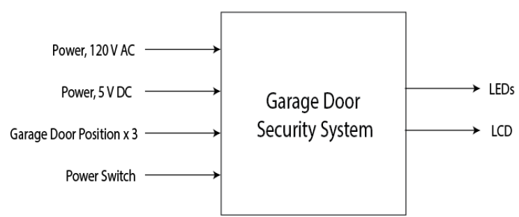
Figure I. Garage Door Security System Level 0 Block Diagram.
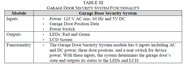
Figure I and Table III below show the Level Zero overall system functionality. Figure I depicts the system’s overall inputs and outputs at a very basic understanding. Table III gives more details and explains what each of the inputs and outputs mean. It also contains a functionality description to tie all the inputs and outputs together.
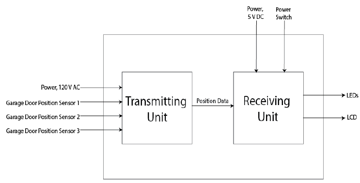
Figure II. Garage Door Security System Level 1 Block Diagram.
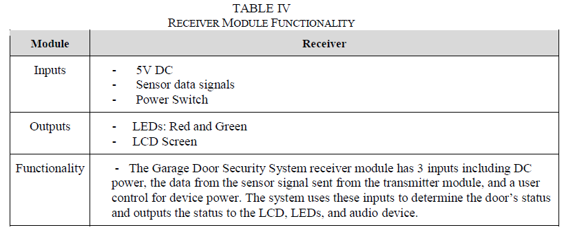
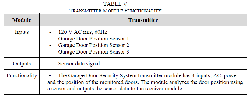
Figure II, Table IV and Table V correspond to the Level One decomposition for the Garage Door Security System. Figure II has two subsystems, the receiver and the transmitter, that make up the whole system. The only link between the two subsystems consists of a wireless connection that transmits the door position data from the transmitter to the receiver. Table IV and Table V breakdown and explain each of the inputs and outputs to the subsystems to give a better understanding of the system.
PROJECT PLANNING
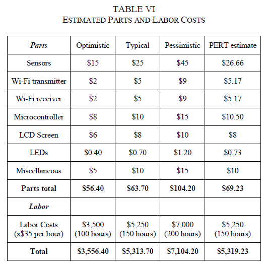
Table VI above represents the estimated costs associated with the Garage Door Security System. The parts and their prices listed may change, however these provide a good starting point for the project fundamentals. The labor costs come from a $35/hour rate. The Gantt Chart and the PERT estimate helped derive the total hours for each specific task. Totaling them all up gives an estimated representation of labor costs. Adding the parts total and the labor total gives the estimated cumulative total for system design and development.
PROJECT DESIGN
Design Concept
The Garage Door Security System relies on hardware and software. The system utilizes two microcontrollers, one for the transmitter side and one for the receiver side. The transmitter side gathers data from up to three magnetic sensors that are easily mounted to most doors. The sensor data is sent to the receiver using Wi-Fi modules where the receiver interprets the data and alerts the user using an LCD display and two different color LEDs.
- Hardware Design
- Software Design
TESTING
The Garage Door Security System consists of many parts and components that work together to complete the fully functional system. During development and testing, each component was isolated as much as possible and tested individually to ensure we could communicate and interface with it properly before introducing it to the system. Working with the Arduino Uno and the Arduino Mega was straightforward with little problems encounter that were directly related to the microcontrollers.
The next component to test was the sensors. We tested the sensors by applying 5 volts to one of the wires and ground to the other, and viewing the output on the oscilloscope and measuring how far the magnet can to be from the Reid switch for it to read a high logic level. Once we had this information, we knew how to interface our sensors as well as how we would have to physically set them up to accomplish what we needed them to do. The last major component to test individually was the ESP8266 Wi-Fi module.
CONCLUSION AND FUTURE WORK
The Garage Door Security System, in its current state, accomplishes the goals we set and functions as required. The system is able to connect to the user’s home Wi-Fi network and send updates to a web server from the transmitter, and the receiver is able to connect to the Wi-Fi and get the updated information and display it wirelessly in the house.
The transmitter is powered by a wall adapter so the user doesn’t have to worry about replacing batteries, and the receiver is powered by batteries so that it can easily be moved throughout the house. However, this system has a lot of room for improvements. Currently, it is a prototype and isn’t packaged. A big improvement would be designing PCB’s for the transmitter and receiver to clean up wiring and greatly reduce the size of the system. This hardware step is critical in order to make the system marketable and to continue the development.
Another area for future improvements is to reduce power consumption, particularly for the receiver. The receiver has a lot of current draw, the Arduino, a rather large backlit LCD display, LEDs, and a Wi-Fi module that draws a lot of current while transmitting and receiving data. The battery life is a huge limiting factor in the everyday use of this system and needs to be addressed to make the system more desirable.
The last major area for future work is the implementation of connecting the system to the Wi-Fi network. Currently, this is accomplished manually by entering the Wi-Fi credentials in the code. This only needs to be done once, however the system currently doesn’t have a method for users to directly enter their Wi-Fi credentials into the system.
Source: California Polytechnic State University
Authors: Trevor Lehr | Austin Williams
>> More Wireless Projects using Arduino for Engineering Students
>> More Wireless Hacking Projects for Wi-fi Enthusiasts for Final Year Students
>> More Wireless Projects Using Microcontroller for Final Year Students