ABSTRACT
Carbon nanotubes (CNT) have been developed in recent decades for nanodevices such as nanoradios, nanogenerators, carbon nanotube field effect transistors (CNTFETs) and so on, indicating that the application of CNTs for nanoscale electronics may play a key role in the development of nanotechnology. Nanorobotics manipulation systems are a promising method for nanodevice construction and assembly.
For the purpose of constructing three-dimensional CNTFETs, a nanorobotics manipulation system with 16 DOFs was developed for nanomanipulation of nanometer-scale objects inside the specimen chamber of a scanning electron microscope (SEM). Nanorobotics manipulators are assembled into four units with four DOFs (X-Y-Z-θ) individually.
The rotational one is actuated by a picomotor. That means a manipulator has four DOFs including three linear motions in the X, Y, Z directions and a 360-degree rotational one (X-Y-Z-θ stage, θ is along the direction rotating with X or Y axis). Manipulators are actuated by picomotors with better than 30 nm linear resolution and
SYSTEM SETUP
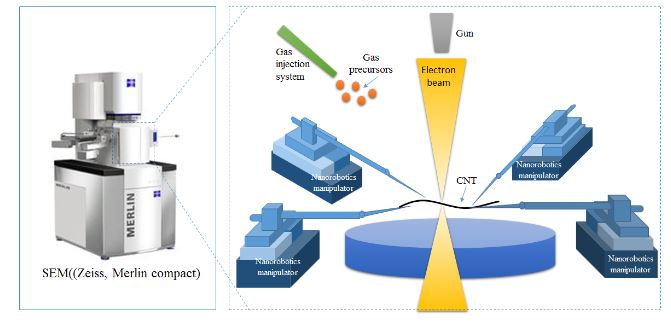
Figure 1. SEM based nanorobotics manipulation system
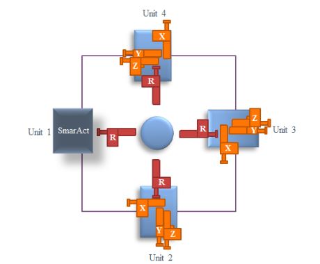
Figure 2. Four units of the nanorobotics manipulation system
In order to manipulate nanoscale objects with AFM cantilever in 3D space for constructing nanostructures and devices inside an SEM, a SEM system with 16 degrees of freedom was introduced to obtain a real-time monitor for nanomanipulation. The image resolution of the SEM is about 1.5 nm with an accelerating voltage of 30 kV.
Figure 1 indicates the nanorobotics manipulation system designed inside the SEM for the purpose of constructing three-dimensional CNTFETs. Four nanorobotics manipulators were symmetrically distributed and pairwisely set opposite to each other inside the SEM. The nanorobotics manipulators were divided into four units named Unit 1, Unit 2, Unit 3, Unit 4, respectively, as depicted in Figure 2.
THEORETICAL MODEL
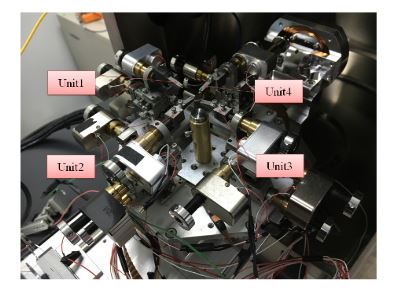
Figure 4. The designed nanorobotics manipulators inside the SEM
Since these four units have a similar structure despite of their different positions, here we just introduce the design and kinematics of nanomanipulator Unit 1 as a representative example. Figure 4 displays the real structure of the designed nanorobotics manipulators inside the SEM.
MANIPULATION STRATEGY AND VISION FEEDBACK CONTROL
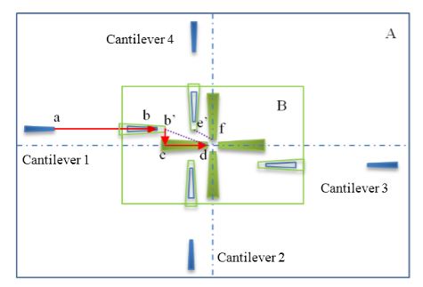
Figure 7. Path planning of each AFM under low and high magnification conditions
Figure 7 shows the different path planning of each AFM cantilever under low and high magnification conditions. End-effectors with blue color are under low magnification presented in region A. The green colored one is under high magnification presented in region B. The center of focused beam area should remain at its position so that the center of SEM images would not change under different magnification.
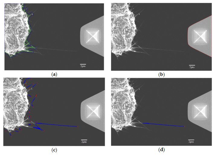
Figure 10. Recognition of CNT and AFM cantilever; (a) Schematic diagram of the new and old boundaries of the substrate
The AFM cantilever can be recognized through the barycenter which is shown with red line in Figure 10b. Since the substrate and the AFM cantilever have been recognized from SEM images, only the CNTs remain. By using the profile feature of CNTs, they can be selected from the SEM image. As shown in Figure 10c, the blue lines represent CNTs, and the red points are the tips of the CNTs.
EXPERIMENTAL IMPLEMENTATION
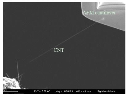
Figure 13. CNT picked up with AFM cantileve
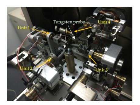
Figure 14. Experimental setup inside the SEM
The application of the developed nanorobotics manipulation system implemented is the controlled pick-up and place manipulation onto multi-tip test. At first, an individual CNT picked up by the AFM cantilever in a nanorobotics manipulator is shown in Figure 13. The diameter of the CNT is between 40–60 nm. The length of the CNT is about 12 μm. Then, four nanorobotics manipulators with two AFM cantilevers and two tungsten probes as end-effectors are installed in the vacuum chamber depicted in Figure 14. End-effectors with the same probes were symmetrically arranged inside the SEM.
CONCLUSIONS AND OUTLOOK
A nanorobotics manipulation system with 16-DOF was designed and developed for 3D nanomanipulation of nanometer-scale objects inside the specimen chambers of scanning electronic microscopes (SEM). Manipulators were divided into four units. Each manipulator has 4-DOF with three linear motions in the X, Y, Z directions and a 360-degree rotational one. Manipulators were actuated with picomotors with better than 30 nm linear resolution and Download Project <1 micro-rad rotary resolution.
A series of kinematics derivations of these four manipulators based on the Denavit-Hartenberg (D-H) notation were established. The common working space of the end effector was 2.78 mm by 4.39 mm by 6 mm. The manipulation strategy for picking up CNTs and placing them onto other cantilevers with a designed operation sequence was established. The vision feedback control for multi-manipulators operating inside the SEM chamber was also discussed.
Finally, the application of the designed nanorobotics manipulation system was described by successfully testing of the pickup-and-place manipulation of an individual CNT onto the four probes. The experimental result have shown that a single carbon nanotube with a length of 12 μm and a diameter within 40–60 nm was successfully used in a pickup-and place task with this nanorobotics manipulation system based on the proposed manipulation strategy.
Source: Soochow University
Authors: Zhan Yang | Yaqiong Wang | Bin Yang | Guanghui Li | Tao Chen | Masahiro Nakajima | Lining Sun | Toshio Fukuda