ABSTRACT
Robot tactile sensation can enhance human–robot communication in terms of safety, reliability and accuracy. The final goal of our project is to widely cover a robot body with a large number of tactile sensors, which has significant advantages such as accurate object recognition, high sensitivity and high redundancy. In this study, we developed a multi-sensor system with dedicated Complementary Metal-Oxide-Semiconductor (CMOS) Large-Scale Integration (LSI) circuit chips (referred to as “sensor platform LSI”) as a framework of a serial bus-based tactile sensor network system.
The sensor platform LSI supports three types of sensors: an on-chip temperature sensor, off-chip capacitive and resistive tactile sensors, and communicates with a relay node via a bus line. The multi-sensor system was first constructed on a printed circuit board to evaluate basic functions of the sensor platform LSI, such as capacitance-to-digital and resistance-to-digital conversion. Then, two kinds of external sensors, nine sensors in total, were connected to two sensor platform LSIs, and temperature, capacitive and resistive sensing data were acquired simultaneously.
Moreover, we fabricated flexible printed circuit cables to demonstrate the multi-sensor system with 15 sensor platform LSIs operating simultaneously, which showed a more realistic implementation in robots. In conclusion, the multi-sensor system with up to 15 sensor platform LSIs on a bus line supporting temperature, capacitive and resistive sensing was successfully demonstrated.
TACTILE SENSOR NETWORK SYSTEM
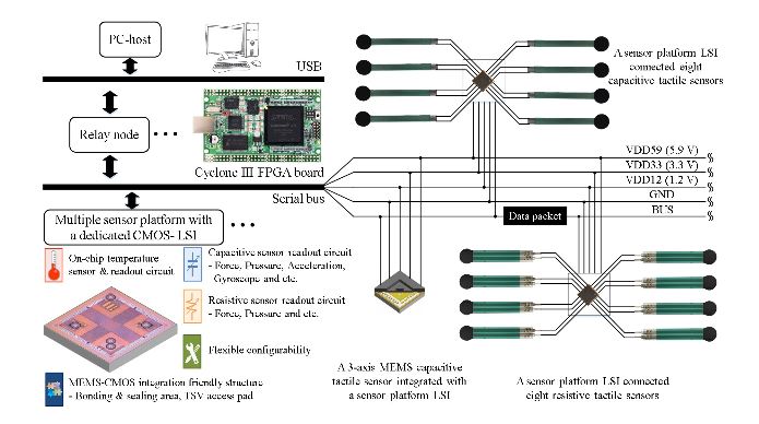
Figure 2. Proposed serial bus-based tactile sensor network system with multiple sensors using the sensor platform LSIs (Large-Scale Integration) on a shared bus line
Figure 2 shows the overview of the sensor system we propose. Each sensor platform LSI can be configured for operating at either capacitive or resistive sensing mode. In the capacitive sensing mode, the sensor platform LSI processes signals from eight capacitance channels. Each capacitance channel can connect a capacitive type sensor. These eight capacitance channels can also be used for a three-axis MEMS capacitive sensor.
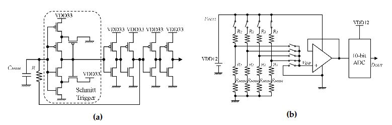
Figure 4. Diagrams of analog-to-digital converter circuits: (a) capacitance-to-frequency converter circuit; (b) resistance-to-voltage converter circuit
As shown in Figure 4a, the capacitance-to-frequency converter circuit is based on a resistor-capacitor oscillator with a Schmitt-trigger circuit. The converter circuit frequency f[Hz] is determined by its RC time constant, and its two designed threshold values.
SENSOR PLATFORM LSI EVALUATION RESULTS
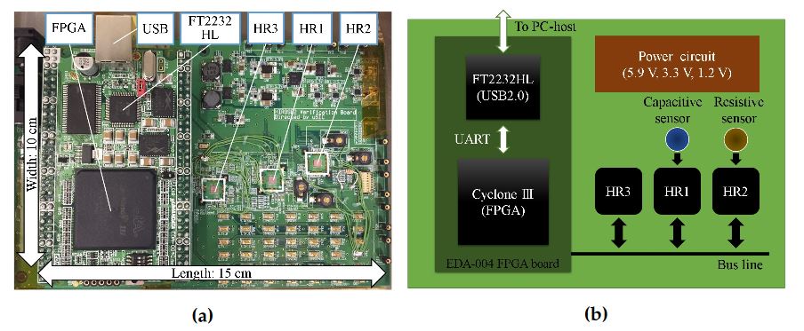
Figure 5. Evaluation board for sensor platform LSI test: (a) photograph; (b) schematic diagram
As shown in Figure 5, we fabricated a Printed Circuit Board (PCB) to evaluate the sensor platform LSI. On this evaluation board, three sensor platform LSIs (HR1, HR2 and HR3) have been implemented and connected to a relay node through the same bus line.
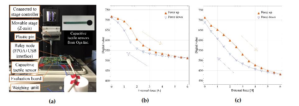
Figure 7. Capacitive tactile sensor evaluation: (a) evaluation setup
As shown in Figures 7a and 8a, to evaluate capacitive and resistive tactile sensors, a capacitive tactile sensor was connected to a sensor platform LSI (HR1), and a resistive tactile sensor was connected to another sensor platform LSI (HR2). By operating the movable stage in the z-axis (Mark-204-MS, SIGMA KOKI Co., Ltd., Tokyo, Japan), the external force can be applied on the sensor through a plastic pin.
EXPERIMENTS ON A REAL-TIME DATA ACQUISITION SYSTEM
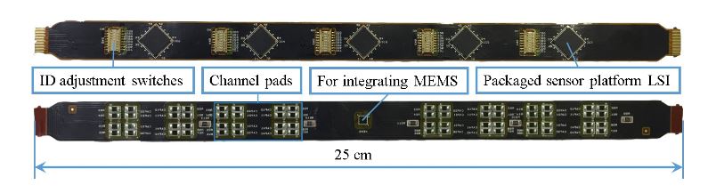
Figure 10. Photograph of Flexible Printed Circuits (FPC) cable with five sensor platform LSIs
As shown in Figure 10, five sensor platform LSIs are implemented in one cable. Sensor platform LSIs and ID switches are mounted on one side of the cable. On the other side of the cable, resistive and capacitive channel pads are mounted. These pads are used to connect z-axis resistive or capacitive tactile sensors by soldering.
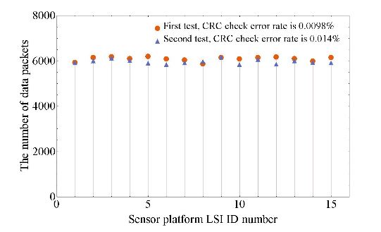
Figure 12. Data receiving results when 15 sensor platform LSIs were operating simultaneously
For the demonstrated multi-sensor system with 15 sensor platform LSIs, from Figure 12, the calculated sampling frequency is 146 Hz (the minimum of the number of received data packets 5859 divided by 40 s), which is much higher than the systems shown in the Table 1. There are eight capacitance-to-digital converters in each sensor platform LSI.
CONCLUSIONS
In this paper, we present the concept of our serial bus-based tactile sensor network system with the sensor platform LSI. Three types of sensors—temperature sensors, capacitive and resistive tactile sensors—can be included in this sensor system. An evaluation board was fabricated to test basic functions of the sensor platform LSI such as the capacitance-to-digital and resistance-to-digital converters, which function well as designed.
Then, based on the evaluation board, we demonstrated the multi-sensor system by using one PC-host, one relay node, two sensor platform LSIs and nine tactile sensors, which showed the implementation of the multi-sensor system with three kinds of sensors—on-chip temperature sensor, off-chip capacitive and resistive tactile sensors.
Finally, we used the FPC cables to demonstrate our multi-sensor system with one PC-host, one relay node, 15 sensor platform LSIs and 12 tactile sensors for real robot use. In conclusion, the multi-sensor system with up to 15 sensor platform LSIs on a bus line supporting temperature, capacitive and resistive sensing was successfully demonstrated. As a next step, we will install more sensor platform LSIs in the multi-sensor system and measure its features related to the data congestion and collision on the shared bus.
Source: Tohoku University
Authors: Chenzhong Shao | Shuji Tanaka | Takahiro Nakayama | Yoshiyuki Hata | Travis Bartley | Yutaka Nonomura | Masanori Muroyama