ABSTRACT
In order to solve the College of Engineering and Computer Science facility access problem, an automated system that provides exterior doors with a time schedule and allows authorized users to gain access to the facility after hours was developed. A microcontroller based system has been designed to interface with a personal computer. The system designed within this thesis can be used as a starting point for multiple facility access control systems.
This thesis will describe the design, integration, test, and final delivery of a facility access system that incorporates the Texas Instruments MSP430 microcontroller, a magnetic card swipe reader, and software developed in Microsoft Visual Basic. Net to provide a reliable and robust system for the College of Engineering and Computers Sciences needs.
PROBLEM STATEMENT
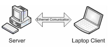
Figure 1: Door Server Block Diagram
As stated in the Introduction, the current facility access system in place for the College of Engineering and Computer Science is in need of a slight modification. Many of the mechanical parts have stopped working correctly, a daily schedule of when the facility should be opened to the public is needed, and a way to track users that gain access to the facility after hours would help facility management in preventing theft of property.
HARDWARE DESIGN
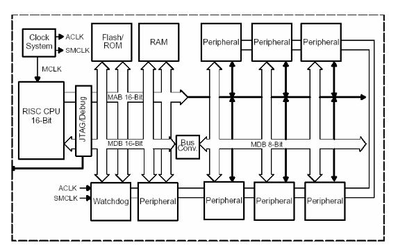
Figure 3: MSP430 Architecture
The clock system used for the MSP430 was designed specifically for battery-powered applications. A low frequency auxiliary clock is driven directly from a common 32-kHz watch crystal. This auxiliary clock can be used for a real-time self wake-up function. Also on the MSP430 is an integrated high-speed digitally controlled oscillator.
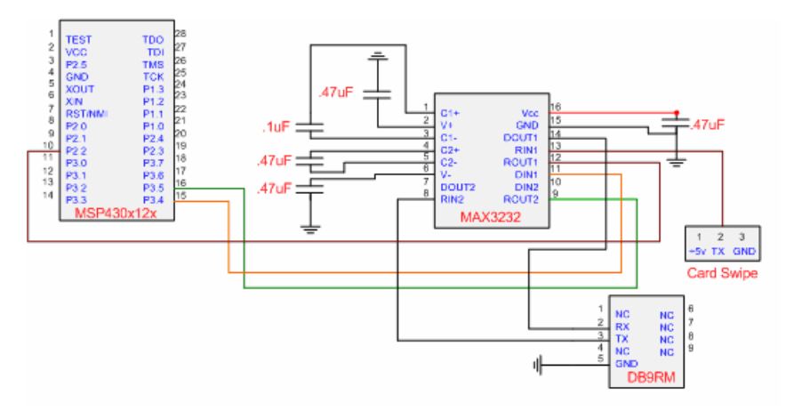
Figure 6: MAX3232 Interface diagram
To handle serial communication between the MSP 430, magnetic card swipe reader, and the lap top computer, a MAX3232 chip by Texas Instruments will be used. Figure six shows the MAX3232 interface to the MSP430, magnetic card swipe reader and the DB9 port for serial communication with the laptop.
MICROCONTROLLER SOFTWARE DESIGN
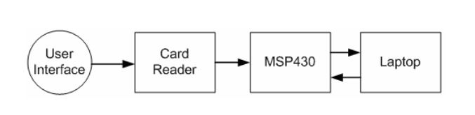
Figure 10: High Level Architecture
The software to be produced will provide a computerized interface between facility administrators and individual exterior doors. Specifically the MSP430 will accept commands from the client interface which will determine if doors should be unlocked or locked. Also, the MSP430 will send data from the magnetic card swipe reader to be processed. A high level architecture is shown in figure 10.
HOST SOFTWARE DESIGN
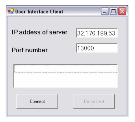
Figure 16: Client GUI
Once a system is in place, a laptop computer will connect to the local Ethernet and the client application will begin. Figure 16 shows the client graphical user interface (GUI). The GUI is designed to be very simple but configurable by any user.
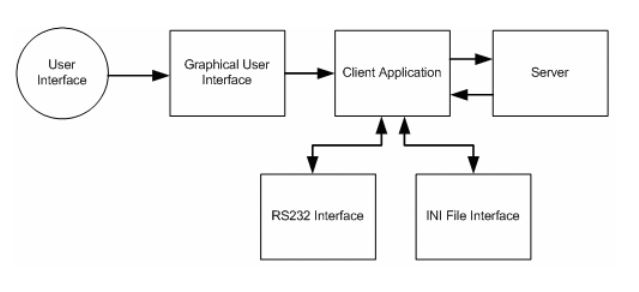
Figure 17: High Level Client Architecture
Figure 17 shows a high level overview of the client software. It consists of the GUI interface, the client application, RS232 interface, INI file interface and the connection to the server. Each part of the client software provides information to the client which is then passed on to the server.
DATABASE DESIGN
The design of the tables for the door controller database is implemented in such a way that allows them to have expandability and flexibility. It is expected that the system will continue to grow with future modifications. The database is made up of six tables. Each table contains information related to users or configurable parameters needed for configuring of the server correctly.
IMPLEMENTATION–NON DESIGN
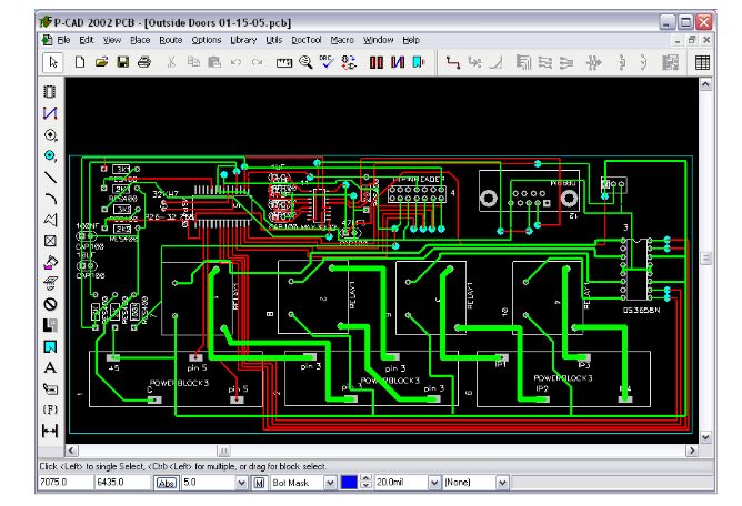
Figure 35: Altium PCAD 2002
Once all hardware components were selected, a custom PCB had to be made. To make the PCB board, Altium PCAD 2002 was used. This software provides all the necessary features to design each individual component and transpose the electrical wiring schematic to the PCB board. Figure 35 shows a screen shot of Altium PCAD 2002. The current display of the PCB board is displayed on the screen.
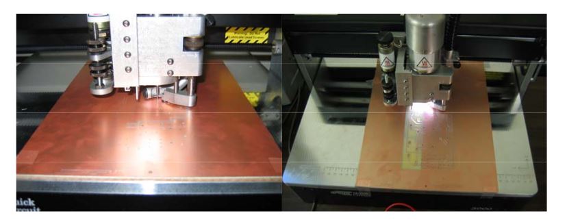
Figure 37: Milling Machine In Use
Figure 37 contains two photos of the milling machine at work. The picture on the left shows the milling of the isolation layer and the picture on the right shows the milling of the rub out layer.
TESTING
This chapter discusses the testing involved with the door controller interface system. Both hardware and software testing will be discussed. Test cases will be examined and the testing process will be reviewed. Hardware testing is a very complex and time consuming process. From the beginning of this project, much time was spent looking for components that would work with each other.
CONCLUSION
The development of door controller interface system is the start of a new entry in to facility access. The system has the ability to allow facility management to gain control over exterior doors and possibly grow to control all doors within the facility. The system developed provides a working solution to the current problem that the two Engineering buildings are having. The door controller interface system is able to provide facility management with an easy interface to control all exterior doors.
User will be able to unlock and lock exterior doors from server, update times that doors should be locked or unlocked. Also, a record of all users trying to gain access to the facility will be kept. This log will contain the users name, card number, data and time they wanted access, and if access was granted. All of the above listed features give control back to facility management on whom and when people can enter the facility. The current door interface system is a great start to solving the Colleges facility access problem, but m any hardware and software upgrades could be used in the future.
The hardware for the exterior doors needs be controlled all by the microcontroller. The currently used laptop should be removed from the equation and all data should be stored on onboard memory on the interface board. Also, a direct Ethernet communication link should be made with the microcontroller. Although these features are not implemented on this version, they are very doable. Another upgrade for the hardware should include the integration for all interior doors. This would be a major upgrade for the interior doors, but a great addition. For the software, if the client applicant was removed the server would need modifications to communicate directly with the microcontroller.
Source: University of CentralFlorida
Author: Thomas Fulbright