ABSTRACT
This paper presents a telemetry system used in a combined trilateration method for the precise indoor localization of the elderly who need health monitoring. The system is based on the association of two wireless technologies: ultrasonic and 802.15.4. The use of the 802.15.4 RF signal gives the reference starting time of the ultrasonic emission (time difference of arrival method).
A time of flight measurement of the ultrasonic pulses provides the distances between the mobile node and three anchor points. These distance measurements are then used to locate the mobile node using the trilateration method with an accuracy of a few centimetres. The originality of our work lies in embedding the mobile node in clothes.
The system is embedded in clothes in two ways: on a shoe in order to form a―”smart” shoe and in a hat in order to form a―”smart” hat. Both accessories allow movements, gait speed and distance covered to be monitored for health applications. Experiments in a test room are presented to show the effectiveness of our system.
LOCALIZATION AND NAVIGATION SYSTEM
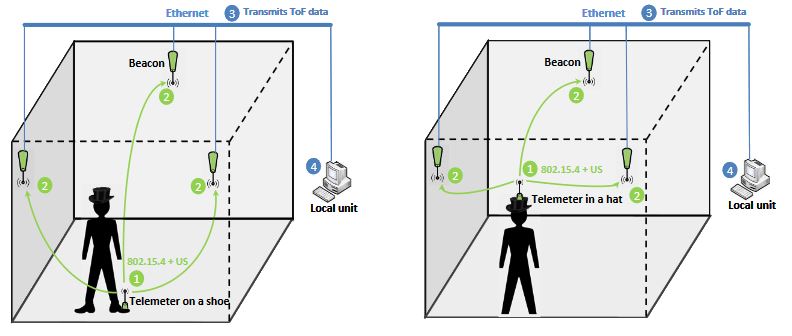
Figure 1. System architecture: Telemeter embedded on a shoe or in a hat
The system has two main functionalities. The first is to estimate the position of the user, typically a pedestrian in an indoor environment, and the second is to calculate the movements of the user. The telemetry system is embedded on the person in two ways: on a shoe in order to form a ―”smart” shoe and in a hat in order to form a ―”smart” hat. The system architecture is shown in Figure 1.
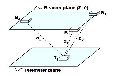
Figure 2. Layout of 3D localization system
In this study, three anchor points are used to extract the position of the mobile node in a 3D indoor environment. Figure 2 shows three anchors points called Beacons (B1, B2 and B3) that act as reference points in a known coordinated system. The mobile node (Telemeter T1) transmits RF and ultrasonic signals and all the Beacons can determine their own distances relative to the Telemeter position by measuring the ToF of the US signal.
HARDWARE PRESENTATION
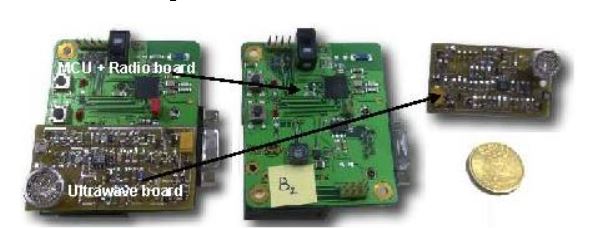
Figure 5. RF and ultrasonic devices
The prototype (Figure 5) comprises two parts separated in two specific boards connected through dedicated Programmable Input/Output (PIO). The first board contains the Micro Processor Unit (MPU) and a radio modem, while the second board is dedicated to the ultrasonic emission/reception pulses. The details of the hardware architecture and the system block diagram have previously been presented.
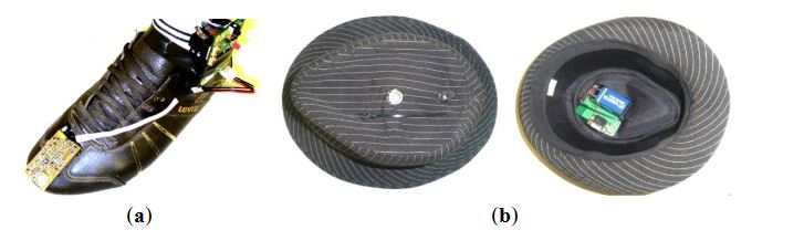
Figure 7 . (a) Device embedded on a shoe. (b) Device embedded in a hat
The Telemeter is embedded in clothes in two ways: on a shoe in order to form a―”smart” shoe and in a hat in order to form a―”smart” hat, as shown in Figure 7.
SOFTWARE PRESENTATION
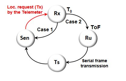
Figure 9. Beacon state machine
The Beacon node is always in reception mode sensing (Sen) localization requests. As soon as the Beacon node receives (Rx) a localization request (Tx) by the Telemeter, a timer is started (T0). The Beacon waits for an ultrasonic pulse; at this level two cases are possible, as shown in Figure 9.
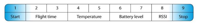
Figure 11. Serial frame format
After the Beacon has computed the ToF, a serial data frame is sent to the Ethernet board from the MPU. The format of the frames exchanged between the MPU and the Ethernet board is shown in Figure 11. The three Beacons send a frame allowing the position of the Telemeter to be extracted by the trilateration method.
SYSTEM CHARACTERIZATION
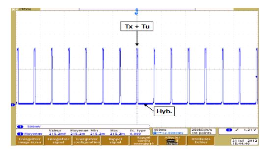
Figure 14. Current consumption of the Telemeter
We observe in Figure 14 current peaks (48.8 mA) that correspond to sen ding simultaneously RF and ultrasonic signals (Tx + Tu) every 256 ms. The rest of the time, the Telemeter is in hibernation mode (Hib.) and consumes very little energy (10 μA).
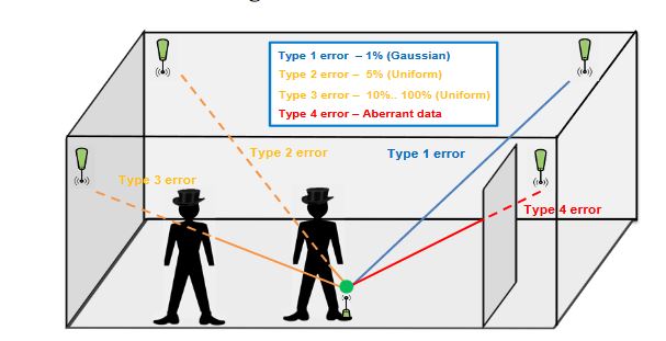
Figure 16. Error sources
The coverage of our system in this configuration is 30 m². An empty room is the ideal scenario to evaluate the performances of a localization system. In a real environment, the major error sources for an ultrasonic system are related to obstacles (furniture, people, etc.). A study categorizes these error sources into four types, as shown in Figure 16.
FUTURE WORKS
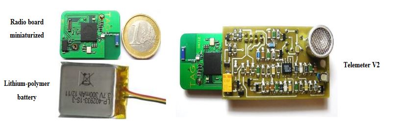
Figure 19. The Telemeter V2
Currently, we are developing a miniature Telemeter in order to embed it easily into a garment. The radio board has been miniaturized, especially by the replacement of the 9 V battery by a lithium-polymer battery rechargeable (3.7 V, 300 mAh). An accelerometer also has been added in order to measure ADL more precisely. The ultrasonic board is being of miniaturization. The prototype V2 is shown in Figure 19.
CONCLUSION
The main objective of this work is to provide a―”smart” garment for monitoring the ADLs of the elderly in institutions or at home. This tool is a Telemeter system embedded in clothes measuring certain mobility parameters and allowing precise localization in an indoor environment. Indeed, by combining this garment with a network of anchor points, a local unit allows the displacements of a person to be monitored in an indoor environment and in real time.
The Telemeter uses an RF 802.15.4 signal to start the ToF measurement of an ultrasonic emission in order to compute the distances between the device worn by the user and three Beacons fixed in the environment. The localization is computed from these distances using the trilateration method. The coverage of the localization system is 30 m². The characterization of static performances shows:
1. good reliability: the standard deviation is 2 cm;
2. good accuracy: the average position error is 10.8 cm.
The mobility parameters are computed using a post processing application to filter measurement points inconsistent with the displacement recorded. Tests were performed with the system embedded on a shoe and in a hat. The characterization of mobility performance shows:
1. good accuracy on distance covered (92.3% in the worst case);
2. good accuracy on gait speed (90.5% in the worst case).
The accuracy in terms of the mobility parameters is acceptable in the context of the monitoring of the elderly at home. Indeed, the goal is to provide certain mobility indicators to health professionals so that they can assess development over the long term. In the case of frail elderly people living at home, these indicators allow earlier intervention in the case of abnormal mobility loss and potentially prevention of further mobility loss.
Source: University Pierre Mendes
Authors: Yoann Charlon | Nicolas Fourty | Eric Campo
>> More Wireless Embedded Projects for Final Year Students
>> More Wireless Energy Projects for Final Year Students