ABSTRACT
This thesis presents the design and implementation of a high-frame-rate oil film interferometry technique (HOFI) used to directly measure skin friction in time dependent flows. Experiments were performed to determine the ability of a high-speed camera to capture oil film interferometry images. HOFI was found to be able to capture these interferometry images at frequencies up to 105 Hz. Steady laminar and turbulent flows were tested.
Transient flows tested consisted of a wind tunnel ramping up in velocity and a laminar boundary layer which was intermittently tripped to turbulence by puffing air out of a pressure tap. Flow speeds ranged from 0 to 108 ft/sec and 10 and 50 cSt Dow Corning 200 dimethyl polysiloxane silicone oil was used. The skin friction was determined from the rate of change of the height of the oil film using lubrication theory.
The height of the oil film was determined from the high speed camera interferogram images using a MATLAB script which determined fringe spacing by fitting a four-parameter sine wave to the intensity levels in each image. The MATLAB script was able to determine the height of the oil film for thousands of interferogram images in only a few minutes with sub-pixel error in fringe spacing. The skin friction was calculated using the oil film height history allowing for the direct measurement of skin friction in time dependent flows.
INSTRUMENT DESIGN
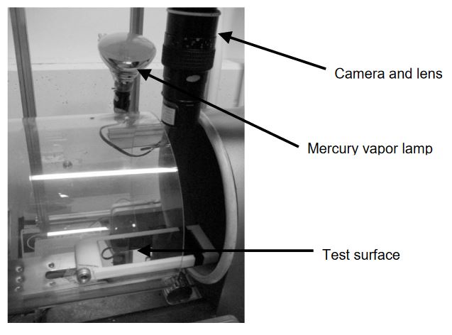
Figure 2.1 : Wind tunnel test section with camera, illumination, and test surface for v1.0 High-Frame-Rate Oil Film Interferometer trials
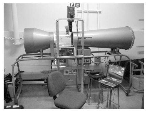
Figure 2.2 : 1-ft diameter indraft wind tunnel
The lower the viscosity of the oil the faster the oil will thin and the changes in the height of the oil will be easier to measure. Mercury vapor lamps were chosen because of their ability to illuminate a large surface area. The lamps were reflected off a diffuse surface and onto the test surface. Figure 2.1 and 2.2 s how a close-up of v1.0 HOFI including camera, illumination, and test surface and the 1 ft indraft wind tunnel.
FRINGE SPACING IDENTIFICATION
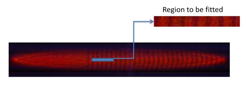
Figure 3.1: Sample interferogram showing the region to be fitted highlighted in blue and reproduced in an enlarged image
The MATLAB script required a minimal amount of input from the user who decided what region of the interferograms was to be fitted. This was usually an area near the leading edge of the interferograms roughly 10 pixels tall and 50 to 100 pixels long, in the spanwise and flow directions respectively. Figure 3.1 shows an example interferogram with the chosen region to be fitted.
WIND TUNNEL RESULTS
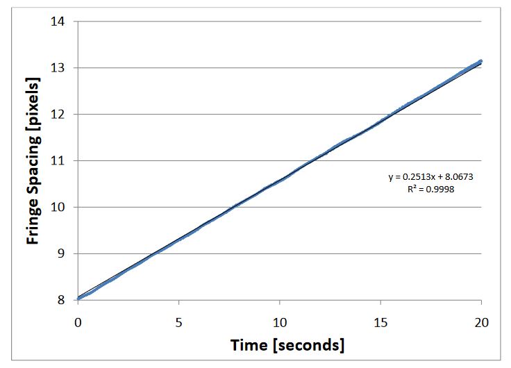
Figure 4.1: Fringe s pacing vs.time: steady laminar flow, 54 ft/sec wind speed, 100 frames per second, 50 mm reversed Nikon lens, 10 cSt dimethylpolysiloxane oil
Testing was performed with wind tunnel velocities ranging from 27 ft/sec to 108 ft/sec. The results from one such test is shown below in figure 4.1. The wind tunnel velocity was 54 ft/sec giving a dynamic pressure of 3.4 psf and a local Reynolds number of about 3 x 10⁵. The distance from the plate leading edge to oil was 8 inches.
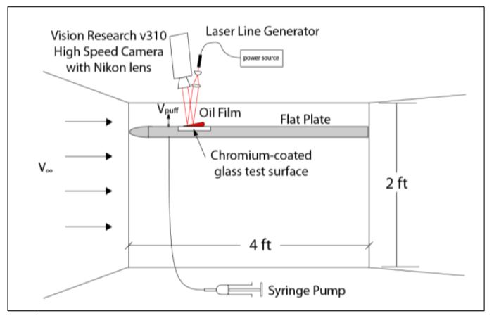
Figure 4.4: Wind tunnel test section schematic for v1.1 HOFI
A second time-dependent scenario was tested which consisted of a laminar boundary layer being intermittently tripped to turbulence. Figure 4.4 shows the v1.1 HOFI schematic which was described in the instrument design chapter. The test surface was placed downstream of a pressure tap which was plumbed to a syringe pump.
CONCLUSION
The oil film interferometry method for measuring skin friction, first developed by Tanner and coworkers in the 1970’s, was adapted for measurement of time-dependent skin friction. This was done by using a high speed camera to capture large numbers of interferograms recorded at a high frame rate. A proof of concept v1.0 and an improved v1.1 high-frame-rate oil film interferometry instruments were designed and used to perform skin friction measurements in a variety of flows.
The proof of concept instrument, called v1.0 high-frame-rate oil film interferometry, was constructed from readily available equipment. The v1.0 HOFI instrument used self-ballasted mercury vapor lamps, a narrow bandwidth filter, a chromium-coated glass test surface, 10 and 50 cSt Dow Corning 200 dimethyl poly siloxane oil, Vision Research’s high speed camera with a general purpose Nikon lens, and a 1 ft diameter indraft low speed wind tunnel.
The average fringe visibility for v1.0 HOFI was 15%. Because the wind tunnel was not fitted with an air filter, the flow was contaminated by particulates which compromised the quality of the interferograms. The optics and illumination used limited the spatial resolution and frame rates that could be employed. Nonetheless, the interferograms obtained occasionally displayed regions of particulate-free oil flow which persisted for a few seconds.
Source: California Polytechnic State University
Author: Jonathan Charles White
>> More Internet of Things (IoT) Diy Projects for Engineering Students