ABSTRACT
For this project, the design, implementation, characterization, calibration and possible applications of a multiple transducer stethoscope apparatus were investigated. The multi-transducer sensor array design consists of five standard stethoscope diaphragms mounted to a rigid frame for a-priori knowledge of their relative spatial locations in the x-y plane, with compliant z-direction positioning to ensure good contact and pressure against the subject’s skin for reliable acoustic coupling.
When this apparatus is properly placed on the body, it can digitally capture the same important body sounds investigated with standard acoustic stethoscopes; especially heart sounds. Acoustic signal inputs from each diaphragm are converted to electrical signals through microphone pickups installed in the stethoscope connective tubing; and are subsequently sampled and digitized for analysis. With this system, we are able to simultaneously interrogate internal body sounds at a sampling rate of 2 KHz, as most heart sounds of interest occur below 200 Hz.
This system was characterized and calibrated by chirp and impulse signal tests. After calibrating the system, a variety of methods for combining the individual sensor channel data to improve the detectability of different signals of interest were explored using variable-delay beam forming. S1 an d S2 heart sound recognition with optimized beam forming delays and inter-symbol noise elimination were investigated for improved discernment of the S1 or S2 heart sounds by a user. Also, stereophonic presentation of heart sounds was also produced to allow future investigation of its potential clinical diagnostic efficacy.
ELECTRONIC AND MULTIPLE-PICKUP STETHOSCOPES-STATE OF THE ART
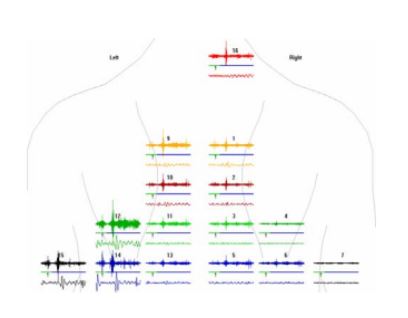
Figure 2.3 Visual Waveform
The application of this product is listening to the lungs, which is much quieter than the heart. The advantage of this product is that it is non-invasive, it records and display the body sounds as shown in Figure 2.3, and it provides specialized signal processing that enable localizing the source of the lung sounds. This pro duct is not for sale in the United States, however indicating that it has most likely not received FDA approval as a diagnostic instrument.
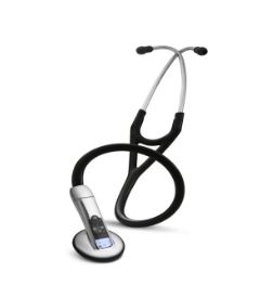
Figure 2.4 Littmann Model 3200 Electronic Stethoscope
In these products, there are three different methods used for the conversion of acoustic sounds to electrical signals. The simplest method is to place a microphone into the chest piece of the stethoscope, as was done in this project. This method has the shortcoming of susceptibility to ambient noise interference. The second, more commonly used method is to employ a piezoelectric crystal as the sound transducer.
MULTIPLE DIGITAL STETHOSCOPE SYSTEM DESIGN
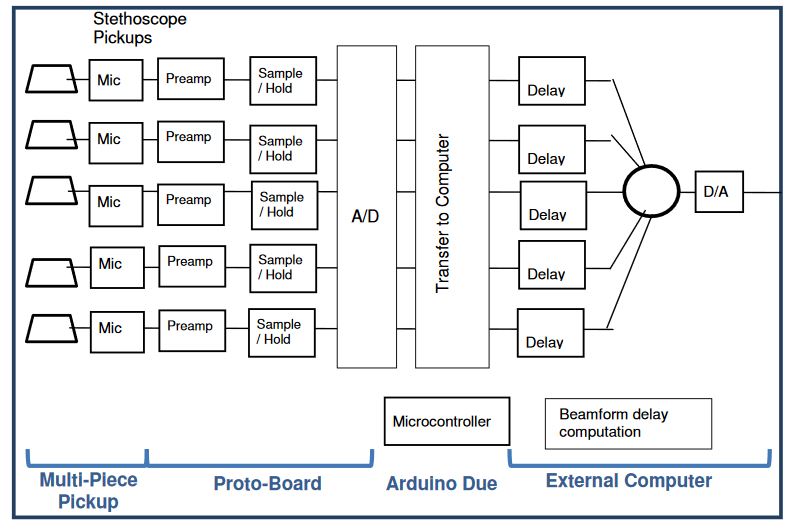
Figure 3.1 Stethoscope System Architecture
A multiple-sensor digital stethoscope was designed for this project to simultaneously acquire heart signals from multiple locations on the body surface. The architecture of the system is shown above. The system architecture is implemented in four major physical components. There is a multi-piece pickup, a prototype circuit board, an Arduino Due board, an d an external computer.
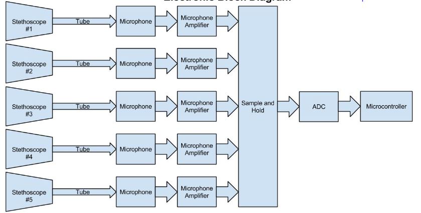
Figure 3.3 Electronic Block Diagram
The front-end electronic architecture of this project is shown in Figure 3.3. There are five stethoscope pickups simultaneously sampled by the microcontroller; with sampled waveforms temporarily saved in the on-board SRAM. The waveform data will then be sent to an external computer to be stored and analyzed.
CHARACTERIZATION AND VERIFICATION
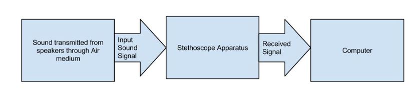
Figure 4.1 Air Coupling Test Block Diagram
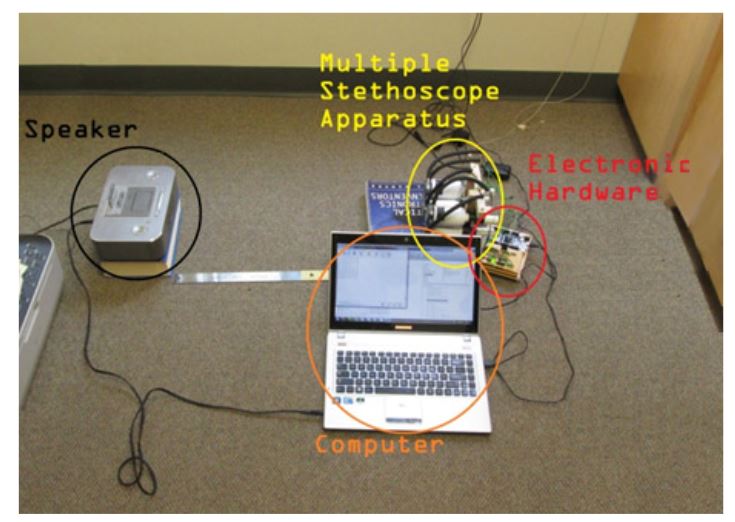
Figure 4.2 Characterization and Verification Test Setup
The block diagram of the test configuration is shown above in Figure 4.1, where the Stethoscope apparatus is the device under test. The basic test setup is shown in Figure 4.2; where the speaker is on the left side of the image and the multiple stethoscope apparatus is on the right side with the electronic hardware and the computer to command and received data. Details of the procedures and MATLAB scripts used in the three system characterization tests can be found in the Appendix I.
OPTIMIZED BEAMFORMING ANALYSIS
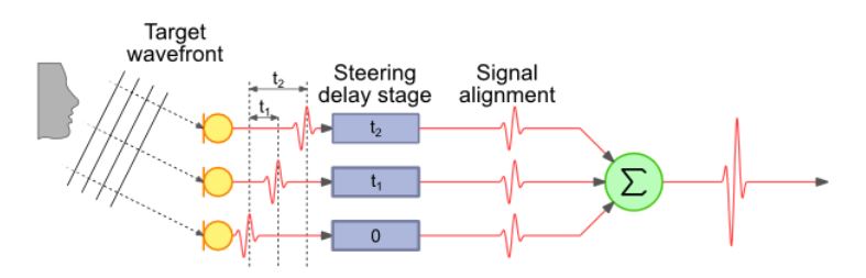
Figure 5.1 Beamforming Example
In standard beamforming, the signals from multiple sensors are repositioned in time so that the signals emanating from a particular source location in space are temporally aligned to reinforce each other, producing a stronger aggregated signal, as shown in Figure 5.1. In so doing, noise signals emanating from other spatial locations will not be properly aligned in the different sensor signals after beamforming delays are applied.
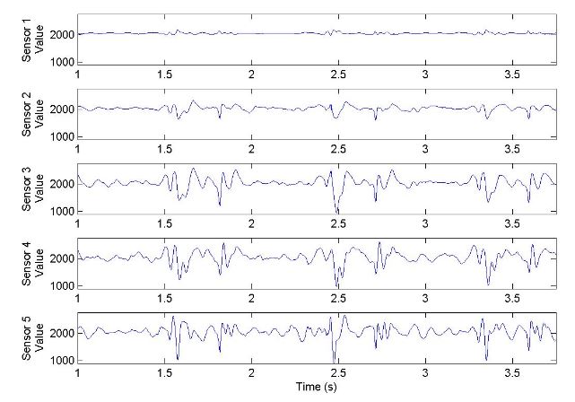
Figure 5.2 Original Sensor Signals
The body sounds were collected from the author, Spencer Wong, who does not have any known heart problems, based on a diagnostic determination made by his primary care physician. Below in Figure 5.2 is a picture of the waveform data collected for this analysis. This data is the same data shown in Multiple Stethoscope Apparatus Body Placement Test section f or Location 2.
FUTURE WORK
There are many improvements that can be made in the electronic design of this project. The most significant work that needs to be done is to have a better wire management, meaning having shorter wire connections between the microphones and the preamplifiers. Long wires can result in noise susceptibility. Also, the system is more liable of breaking with long wires without strain relief. Additional research should be done on using piezoelectric or electromagnetic diaphragm to improve the data recording. This could be a viable solution for removing the tube and the microphone.
CONCLUSION
In conclusion a multiple stethoscope apparatus was designed, built and characterized. The design of the project included designing the electrical, mechanical and software elements for this system; in addition to designing test methods and analysis software to characterize the stethoscope apparatus. Once the design and characterization was achieved, explorations on collecting body sounds were carried out.
Data was gathered from different locations on the body and compared to find the optimal sensor locations to collect data. With the data collected, various method of combining the body sounds for improved listening were explored using different approaches to optimized phase-delay beamformation. Ultimately, all of the beamforming results showed an improvement in signal to noise ratio on the signal features of interest.
This project demonstrated that there is potential for a multiple stethoscope apparatus as an effective and improved tool for listening to the heart. It has provided a “proof of concept” for the basic construction and signal processing required for such as system. While this project wasn’t able to demonstrate the potential benefits of this system for diagnosing clinical issues with a poorly functioning heart, it was successful at providing a starting point for further research on this topic.
Source: California Polytechnic State University
Author: Spencer Geng Wong
>> 50+ Matlab projects for Digital Image Processing for Final Year Students
>> More Matlab Projects using Arduino for Final Year Students
>> 200+ Matlab Projects based on Control System for Final Year Students