ABSTRACT
Some insects or mammals use antennae or whiskers to detect by the sense of touch obstacles or recognize objects in environments in which other senses like vision cannot work. Artificial flexible antennae can be used in robotics to mimic this sense of touch in these recognition tasks. We have designed and built a two-degree of freedom (2DOF) flexible antenna sensor device to perform robot navigation tasks.
This device is composed of a flexible beam, two servomotors that drive the beam and a load cell sensor that detects the contact of the beam with an object. It is found that the efficiency of such a device strongly depends on the speed and accuracy achieved by the antenna positioning system. These issues are severely impaired by the vibrations that appear in the antenna during its movement. However, these antennae are usually moved without taking care of these undesired vibrations.
This article proposes a new closed-loop control schema that cancels vibrations and improves the free movements of the antenna. Moreover, algorithms to estimate the 3D beam position and the instant and point of contact with an object are proposed. Experiments are reported that illustrate the efficiency of these proposed algorithms and the improvements achieved in object detection tasks using a control system that cancels beam vibrations.
MATERIALS
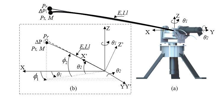
Figure 1. 2DOF flexible-beam sensor: (a) mechanism design and (b) schematic diagram
The motor configuration is shown in Figure 1a, which illustrates the mechanism that is used to hold the multi-axis (F-T) sensor. Two servo-motor sets (motor, gear-box and encoder) are used to drive the sensor, and there is a flexible-beam on the top of the sensor whose initial point at the base of the beam coincides with both motor shafts.
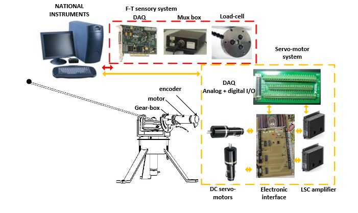
Figure 3. Experimental platform: system setup
Figure 3 shows the system setup, which includes the mechanism, the servo-motor system, the (F-T) sensory system, electronic interfaces and a basic computer to run the system. In order to put together and install each of the necessary component parts, a basic card for an adequate connection was designed (electronic interface), which includes: (1) the servo-motor connectors; (2) servo amplifier connectors.
METHODS
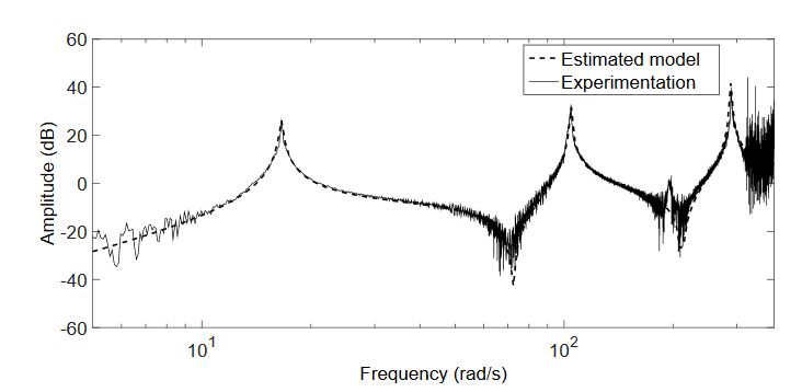
Figure 4. Identification of the model
The magnitude of the frequency response of Equation (2) is also drawn in Figure 4. This figure shows that the experimental dynamics are accurately approximated by model Equation (2) with three vibration modes. Furthermore, it is observed that the sensor measurements are very noisy from 50 Hz–80 Hz.
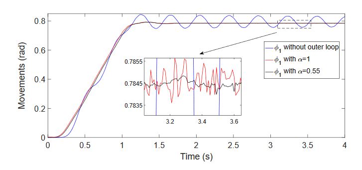
Figure 7. Controlled azimuthal movement
This fact was demonstrated carrying out several azimuthal, attitude and combined azimuthal-attitude antenna movements. Figure 7 compares the performances of these equivalent integer-order and fractional-order phase-lag controllers and shows the higher damping of the second mode achieved by the second controller. These responses were experimentally obtained by using the optotrackexternal sensor mentioned in Section 2.5.
ESTIMATION MECHANISMS
The antenna has to be moved in a controlled way to reach the regions that have to be explored. Then, it is necessary to know in real time the position in the space of all the points of the beam in order to prevent undesired collisions. Moreover, the control algorithm that implements the outer loop uses estimates of the tip position.
RESULTS
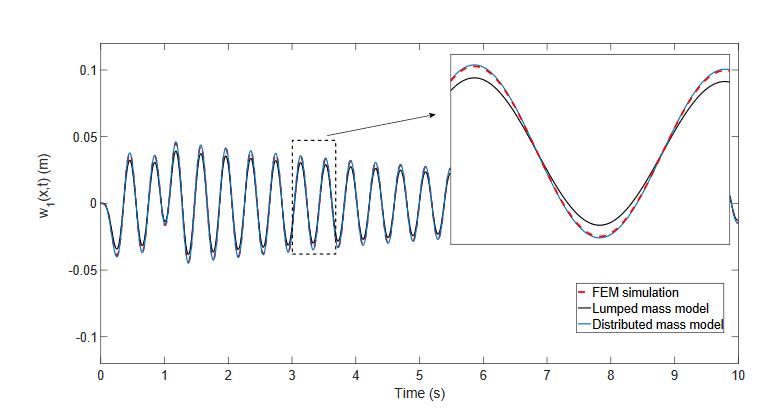
Figure 8. Estimation of the tip deflection in an azimuthal movement (x = l)
Figure 8 shows the tip position deflections obtained in the azimuthal movement, provided by: (a) the finite element program (FEM simulation plot in the figure); (b) Estimator (19) (distributed mass model plot in the figure); and (c) Estimator (20) (lumped mass model plot in the figure).
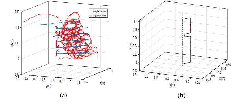
Figure 14. (a) Trajectories performed by the tip of the antenna in the profile recognition experiment
Figure 14a shows the tip trajectories in the first experiment (height spaced 20 mm), measured with the camera-based optical tracking system. In this figure, the trajectory performed using the complete control is shown with blue color, and the trajectory using only the motor control is shown with red color. In Figure 14b, the contacted points are marked over the real object profile (in perspective), blue or red circles in the cases of using the complete control or only the motor control, respectively.
DISCUSSION
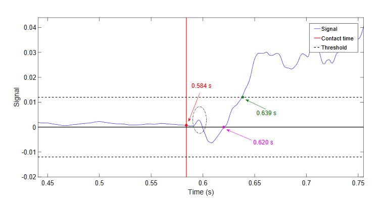
Figure 17. Experimental values of the vertical component of the measured torque in a horizontal movement with impact
The time required by the torque to cross the zero axis and start continuously growing, this time is given by the magenta point marked in Figure 17. This figure shows that the time elapsed from the contact instant to that zero crossing instant is 36 ms, which is similar to the delay previously obtained from the dominant zero. The instant at which the contact is detected is also shown, marked by a green point.
CONCLUSIONS
We conclude from the previous discussion that the estimation algorithms developed in this article are computationally efficient enough to be implemented in our sensing antenna device, which uses a computer of limited capability, in real-time tasks, while achieving a reasonable accuracy. Moreover, we conclude that using a control system that, besides moving the motors, cancels the antenna vibrations, significantly improves the performance of the before algorithms and the overall object detection and recognition tasks. One foreseen application is obstacle detection in mobile robot navigation.
The link length is 0.98 m. Since the height of the robot platform where the antenna is placed is about 30 cm, simple trigonometry allows us to state that our system is able to detect an obstacle on the ground placed 0.9 m beyond the vehicle in the direction of the movement. Since our mobile robot moves at a speed of about 0.4 m/s, this system detects the obstacle at a distance sufficient to permit the change of trajectory or the complete stop of the vehicle before hitting the obstacle. Moreover, some simple recognition tasks of the obstacle can be carried out by our system, which is able to estimate points on the surface of the obstacle with a precision of 2 mm.
Source: Istanbul Gelisim University
Authors: Vicente Feliu-Batlle | Daniel Feliu-Talegon | Claudia Fernanda Castillo-Berrio