ABSTRACT
A circular polarized patch antenna for UHF RFID tag-based sensor applications is presented, with the circular polarization (CP) generated by a new antenna shape, an asymmetric stars shaped slotted microstrip patch antenna (CP-ASSSMP). Four stars etched on the patch allow the antenna’s size to be reduced by close to 20%. The proposed antenna is matched with two RFID chips via inductive-loop matching.
The first chip is connected to a resistive sensor and acts as a sensor node, and the second is used as a reference node. The proposed antenna is used for two targets, serving as both reference and sensor simultaneously, thereby eliminating the need for a second antenna. Its reader can read the RFID chips at any orientation of the tag due to the CP.
The measured reading range is about 25m with mismatch polarization. The operating frequency band is 902–929 MHz for the two ports, which is covered by the US RFID band, and the axial-ratio bandwidth is about 7 MHz. In addition, the reader can also detect temperature, based on the minimum difference in the power required by the reference and sensor.
CP-ASSSMP DESIGN
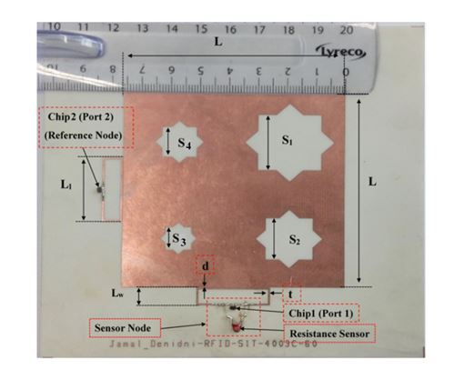
Figure 1. Photo of the fabricated antenna
Since RFIDs are generally used in portable or handheld systems, CP is preferable, because CP can receive a signal at any orientation (orientation diversity), thereby increasing the antenna’s ability to receive a signal and reducing multipath effects. The CP asymmetric-stars shaped slotted microstrip patch antenna (ASSSMP) was therefore designed to provide CP. Figure 1 shows the proposed antenna.
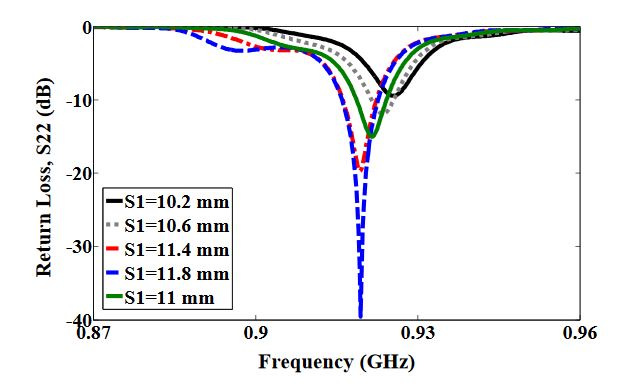
Figure 4. Simulated return loss
Figure 4 shows how increasing the size of one star, (S1), shifts the resonance frequency down to a lower frequency. In addition, the axial ratio based on the electric size of the antenna increases by increasing the slot size as shown in Figure 5. From our parametric study, the best values of S1 are between 10.6 mm and 11.4 mm.
RFID ANTENNA DESIGN
A CP antenna is suitable for RFID applications as it has the ability to receive a signal from any orientation. Many techniques have been used to design CP antennas. The dimensions of the proposed antenna are L = 76.2 mm, S1 = 11 mm, S2 = 8.168 mm, S3 = 4.5 mm and S4 = 6 mm, as shown in Figure 1.
SENSOR DESIGN
A number of RFID sensor designs have been proposed recently. Some of these use one antenna for the reference node and another for the sensor node. Although one antenna is used as both sensor and reference node. However, this application is quite complicated because it requires solar cells and a microcontroller. The antenna proposed here uses a single antenna for both the reference and the sensor nodes, and makes it simple to avoid the effect of random orientation because of its CP.
RESULTS AND DISCUSSION
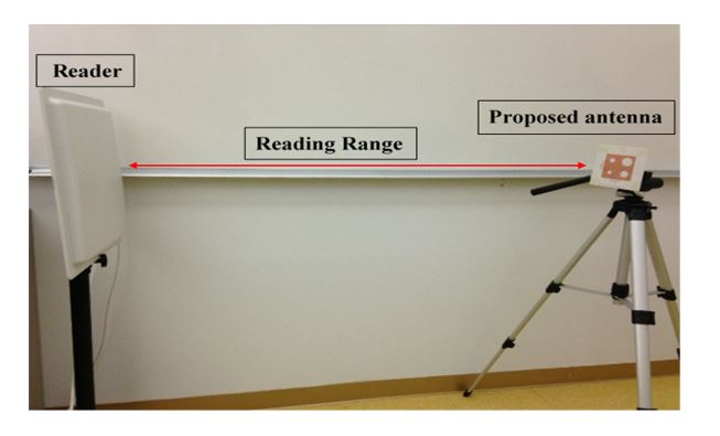
Figure 8. Reading range
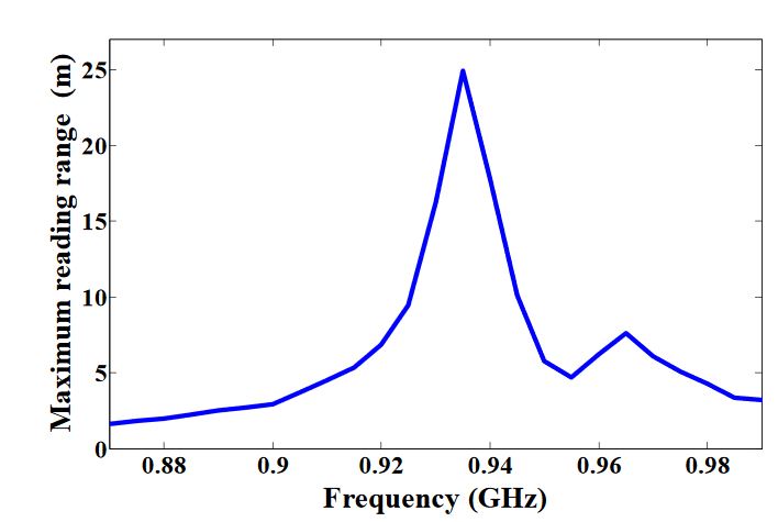
Figure 9. Reading range of the proposed antenna
The reader and the proposed antenna are adjusted as illustrated in Figure 8, and the distance between them is extended until the maximum reading range (25 m) is obtained, as illustrated in Figure 9. A linear polarized reader (GAO) is used in the all measurements. The proposed antenna has an acceptable gain and radiation efficiency of about 3.5 dB and 66%, respectively.
CONCLUSIONS
A circular-polarized asymmetric stars-shaped slotted microstrip patch antenna (CP-ASSSMP) for UHF-RFID sensor applications has been designed, fabricated, and tested. A new antenna concept for generating CP and reducing the antenna size has been presented. The CP-ASSMP uses two RFID ports as reference and sensor nodes.
The minimum required power to activate the reference and resistive nodes at three different resistance values have been measured and plotted. The sensor can detect temperature changes based on the differences in the power requirements. The reading range of the proposed antenna has been compared with several other antenna types.
This new antenna matches the reference and sensor nodes to a single antenna, so they receive the same power under the same environment while eliminating the need for two antennas. Moreover, the reader can read both tags at the same time with a reading range of about 25 m without internal power requirements. Other key advantages of this antenna are its simple fabrication and low cost. Finally, the measured and simulated results show a good agreement.
Authors: Jamal Zaid | Abdulhadi Abdulhadi | Arun Kesavan | Yassin Belaizi | Tayeb A. Denidni
>> Project Report on Microstrip Patch Antenna for Final Year Students