EXECUTIVE SUMMARY
This report documents the design and fabrication processes involved for the creation of an interactive science exhibit for the Grover Beach Exploration Station. This is a student – led senior project advised by Sarah Harding, professor of mechanical engineering, as a part of California Polytechnic State University in San Luis Obispo’s mechanical engineering program. The final product is a fully functioning, durable system that is capable of pumping and recycling water throughout use when users are in its vicinity.
The exhibit is to be considered in 4 main subsystems: basin, plumbing, frame, and sleep mode system. A fiberglass basin that holds all the water in the exhibit sits recessed inside a welded steel frame. Water is pumped through the bottom of the basin from within an enclosed storage area inside the frame, and is recycled back into the water reservoir by placement of two weir valves. A submersible pump powers the exhibit, and is controlled by passive infrared sensors that activate when human presence is sensed within 15ft. While the manufacturing process did reach completion, testing and verification did not. However, proposed testing plans are still included in the appendices of the report for informational purposes.
Divided into distinct sections, this report will enlighten the reader on each part of the design process. First, background research and preliminary design explains the methodology of developing the vision of the final design. Next, different design analysis techniques are given for each respective subsystem of the proposed exhibit. An in – depth description for manufacturing and testing of the completed exhibit is given for each subsystem. Finally, recommendations are given for future improvements to the exhibit, and what kinds of different decisions would be made in the design process if given a second iteration.
BACKGROUND
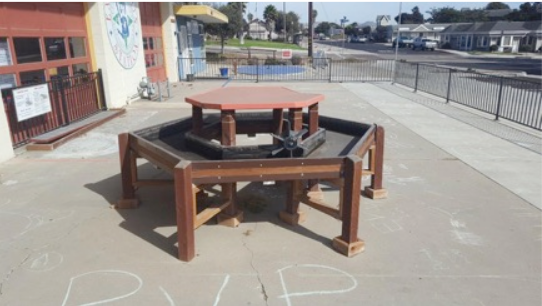
Figure 1: Current water table on the front patio of the Exploration Station. Exhibit is not currently in use
During our first interview with our sponsors, we were made aware of their current water table exhibit that is located on the front patio. We discussed the possibility of refurbishing/restoring the existing table by making the features more interactive, educative, and fun while also structurally reinforcing the table. We were given permission to use the current table in its entirety, to use components of it, or the freedom to design a completely new interactive water exhibit. The current water table exhibit is shown in Figure 1.
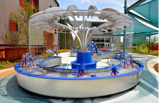
Figure 5: Boss Display exhibit located at DoSeum in San Antonio
Boss Display designs and builds interactive durable and safe exhibits that challenge visitors intellectually and physically, helping to facilitate learning through exploration, experimentation, playful imagination, and shared experience with other visitors and family groups. We searched Boss Display’s portfolio and created a document with a number of their water exhibits that could be used as a benchmark and reference for our future ideation and design. We analyzed each of the exhibits to see how well these exhibits satisfy our customer needs/requirements (for example: weather resistant, transportable, low cost). We were also able to obtain a wide variety of examples of exhibits that demonstrated new and creative features that we could possibly incorporate into our design.
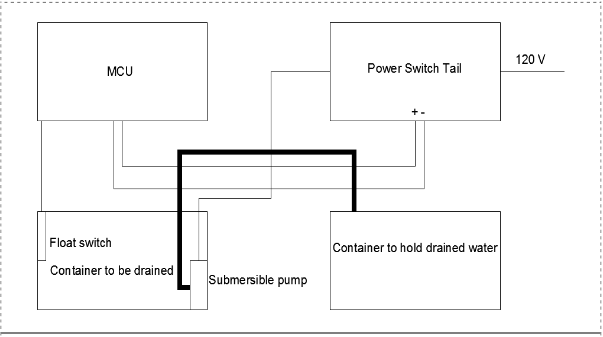
Figure 7: Wiring diagram for draining water from one container to another
Figure 7 shows an automated way to drain water from one container to another when the water level reaches a certain height. When the water level rises in the container to be drained, a component of the float switch goes up and that sends a signal to the microcontroller. The microcontroller then sends a signal to the power switch tail to turn on the relay inside it. The microcontroller is essentially turning on a 120 V line since the power switch tail is connected to an outlet providing that voltage. It’s worth mentioning that 120 V is standard for most homes.
DESIGN DEVELOPEMENT
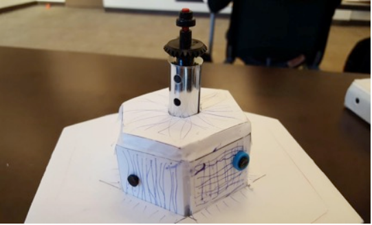
Figure 11: Hexagonal Prototype with Water Wall
Figure 11 shows a hexagon shaped water exhibit with a usable area in the middle. The existing water table at the Exploration Station has the same shape, but with an unusable center area. For this prototype, we placed a water dome at the top of the middle area of the exhibit. The runoff from the water dome cascades down and supplies the water flow necessary for the magnetic water walls to be interactive for its users.
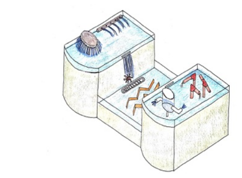
Figure 16: Drawing of feature layout for the Baby B final concept design
The first of our two final design concepts is what our team has named the Baby B. Figure 16 shows the artistic sketch that we have created to help visualize what the Baby B concept would look like. This concept is a “B” shaped table with an extended midsection to be used as a play area catering to smaller visitors (ages three to six) who might not be able to reach up to the taller features. This table shape earned the highest total score in its respective Pugh matrix.
FINAL DESIGN
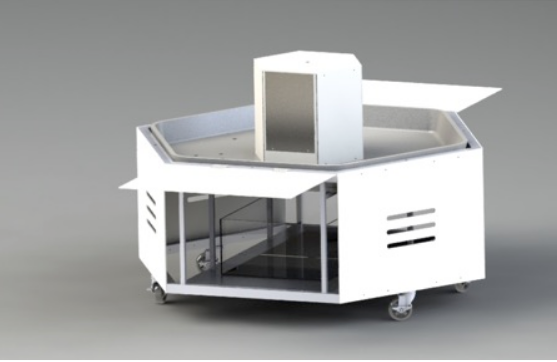
Figure 18: Solidworks rendering of the proposed Exploration Station water exhibit
Our current design has a durable fiberglass basin, a steel frame capable of housing all necessary equipment internally, a submersible pump capable of sending water to a number of outlets across the basin (which can be later utilized for features), and programmed power saving sensors all included in an exhibit that will be aesthetically pleasing and be sure to draw a crowd. The three dimensional model of the proposed exhibit can be seen below in Figure 18.
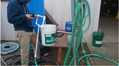
Figure 26: Prototype for the interchangeable water pipes feature
Once the prototype was completed, we set out to test the piping system in order to determine desired flow rate for the outlets. In order to test for flow rates, we hooked up the piping to a water hose and obtained a five – gallon bucket. We proceeded to time how long it took to fill a five – gallon bucket. Figure 26 shows how the piping was connected to a water hose and setup to run the test.
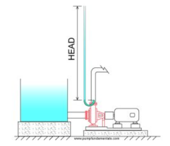
Figure 29: Pump pressure head concept
Now that the overall flow rate for all the features on the exhibit have been determined experimentally, the head required by the pump for this operating point can be calculated using fluid dynamics analysis. The pump that is selected needs to not only produce the desired flow rate of 1306.68 GPH, it must also supply enough head to overcome the head losses in the pipes due to friction, ball valves, and other components that will impede the flow. Required pump head is simply the height that the pump can elevate a column of water. Figure 29 illustrates this concept.
PRODUCT REALIZATION
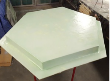
Figure 53 : Basin mold with after the final layer of PVA mold release was applied
One extremely light coat of distilled water makes all of the PVA spread and smooth out, creating the perfect surface finish for the laminate (because PVA is water soluble). Once the basin was left to fully dry, the surface preparation was completed. Figure 53 shows what the basin looked like once the final layer of PVA was applied. If desired, the user could use their finger nail to peel off a tiny bit of the edge of the laminate just to check thickness of the mold release layer.
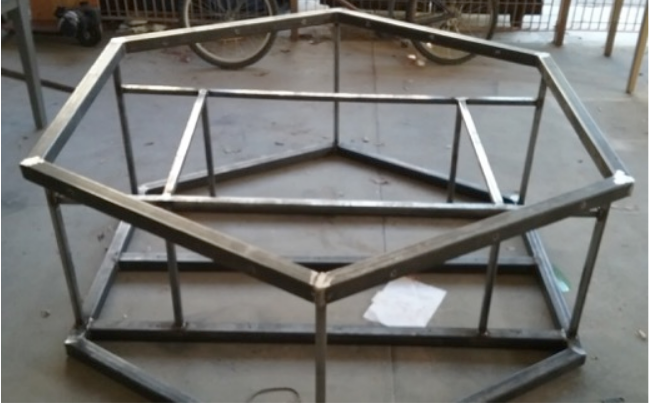
Figure 55 : The completed frame prior to Rust – Oleum paint application
After preparing the siding, the frame was then scrubbed clean to allow us to apply a protective coating to prevent rust. First a coat of primer was painted on all sides of the frame. After 24 hours (once the primer had fully dried), a top coat of grey Rust – Oleum paint was applied. With the protective coating in place the panels could be reattached to the frame. Figure 55 shows the completely painted frame.
DESIGN VERIFICATION
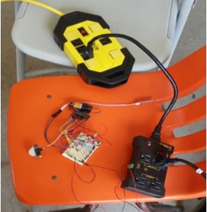
Figure 60 : Testing triggering distances for PIR sensors
The triggering distance of the sensors can be changed from 9ft to 20ft and we tested one sensor at its lowest setting because that is the set ting that will be used for all sensors. We tested this by starting 20ft away from the sensor and walking towards it while monitoring whether motion was detected using the Sleep Mode App. The max distance where motion was detected at the lowest setting of the sensor was 15ft, unlike the datasheet of the sensor stated.
CONCLUSION
Should our team have the opportunity to go back and proceed with a second iteration of exhibit design and manufacturing, there are a number of changes that we would make. First, it is recommended that (should the shape of hexagon be decided on again) then the team should design and machine our own lugs for fixing together pieces of the frame. The number of issues that this geometry created for our team throughout the project was fairly considerable. When the frame steel was cut using the chop saw, inconsistencies in finish tolerances led to us having to improvise the forming of joints. Had we been able to use 60° square lugs (which we were not able to find on the internet) then it would have made frame assembly much easier, and if compatible materials for beams and lugs were chosen, then the two could have been welded together for additional support.
Another change that our team would make is using a material other than stainless steel for the frame of the smaller hexagonal structure in the middle of the basin. The weight of the frame is a concern, and causes a lot of unwanted deflection in the very middle, which can be considered one of the causes for the leaks that we are currently experiencing from the bulkheads in that area. Using another material, such as PVC or some other kind of plastic would be less expensive, easier to manufacture, and place less stress on the extremely valuable basin that it is resting upon.
Additionally, the drains that we have installed do not allow for very much flow out of the basin and the reservoir. More functional drains with a wider valve opening size would be installed in these locations to allow for more efficient draining of the system. Also, for the drain on the reservoir, we did not take into account that the user cannot just attach a hose and funnel the water wherever they want. A certain amount of head is required to move a fluid, and having the outlet tap at the bottom of the tank does not allow for this.
Source: Calpoly
Authors: Alejandro Gonzalez – Smith | Raymond Morales | Heriberto Rodriguez | Nicholas Runyan