ABSTRACT
An algorithm for indoor localization of pedestrians using an improved Inertial Navigation system is presented for smartphone based applications. When using standard inertial navigation algorithm, errors in sensors due to random noise and biasresult in a large drift from the actual location with time. Novel corrections are introduced for the basic system to increase the accuracy by counteracting the accumulation of this drift error, which are applied using a Kalman filter framework.
A generalized velocity model was applied to correct the walking velocity and the accuracy of the algorithm was investigated with three different velocity models which were derived from the actual velocity measured at the hip of walking person. Spatial constraints based on knowledge of indoor environment were applied to correct the walking direction. Analysis of absolute heading corrections from magnetic direction was performed.
Results show that the proposed method with Gaussian velocity model achieves competitive accuracy with a 30% less variance over Step and Heading approach proving the accuracy and robustness of proposed method. We also investigated the frequency of applying corrections and found that a 4% corrections per step is required for improved accuracy.
The proposed method is applicable in indoor localization and tracking applications based on smart phone where traditional approaches such as GNSS suffers from many issues.
BACKGROUND

Figure 2.1: Common INS solution architecture with complementary Kalman filter for drift correction.
The “Navshoe” system introduced by Foxlin is a dead reckoning INS solution with a shoe mounted IMU which employs Zero Velocity Updates (ZUPTs) as the main correction to control the drift. As introduced by Foxlin, complementary Kalman filter is commonly used in these INS based tracking applications to apply the external corrections. This filter allows the tracking of error and applying a correction to the measurement. In addition, Extended Kalman Filter (EKF) and Unscented Kalman Filter (UKF) have been used with non-linear motion models in calculating the position. A basic generic strapdown INS system is shown in figure 2.1.

Figure 2.2: Analysis of different phases of human gait cycle.
“Gait Cycle” is defined as heel strike to next heel strike of the same foot. This cycle goes through two main phases known as “Swing” and “Stance”. From heel contact to the next toe off is called “stance phase” and the foot is in contact with the floor and stationary in this phase. The “swing phase” is from the toe off to the next heel contact and foot is in air in this phase. The actual movement in forward direction happens in the swing phase. This analysis is further shown in figure 2.2 for clarity.
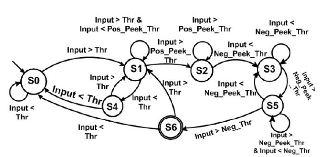
Figure 2.4: State transition for one step in FSM step detection method suggested by Alzantot et al.
Suggested by Alzantot et al., this method tries to match the specific pattern of the step acceleration signal to states and define a step as the transition between those states. State transition is enabled by selecting four different threshold values as shown in figure 2.4 for one complete step.
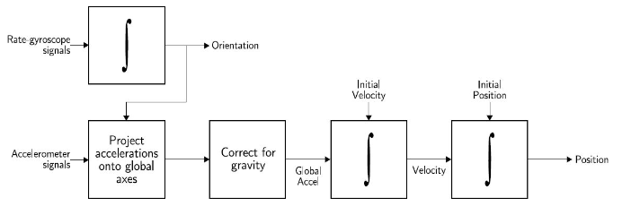
Figure 2.6: Basic strapdown INS algorithm
Due to bias and random errors present in sensor readings, calculated distance deviates from the actual distance exponentially within few seconds. In order to correct that, zero velocity updates have been employed in the foot mounted inertial sensor scenario when the foot is in the “stance” phase. Rather than directly resetting the velocity to zero, the error is maintained as the state in Kalman filter and correction is applied as a measurement to the filter. This is known as the complementary Kalman filter application.
METHODOLOGY
Sensor readings normally include a constant bias error which can be removed based on a precalcualted value. Low pass filtering is performed on sensor measurements signal to remove the random high frequency components. In our system, low pass filtering was only performed on gyroscope signal to identify domain specific spatial constraints. These tasks are performed in the preprocessing step after capturing sensor readings.
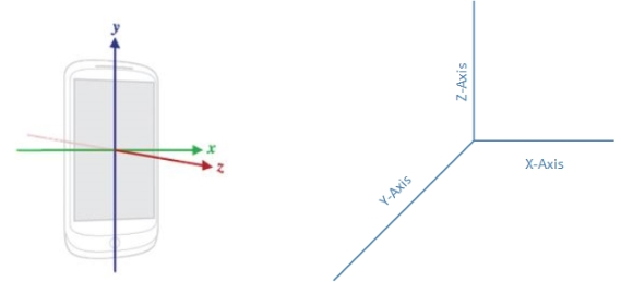
Figure 3.3: Local frame and Navigation frame reference systems used in this experiment.
Due to movement of the device while walking, the orientation of the phone may not align perfectly with the navigation frame. Furthermore, this off set may change while walking. Hence a transformation is needed to convert the readings in local frame in to the navigation frame. Local (phone) frame reference system and the navigation frame reference system, which were used, are shown in figure 3.3.
RESULTS
Experiments were performed in two phases named: calibration phase and test phase. Walking data obtained in the calibration phase was used to find the optimized values for the necessary parameters and then they were used directly in test phase to calculate and compare the results. Variation of accuracy, with the amount of corrections in the proposed method was investigated. For this, ‘Correction Percentage’ was defined as the percentage of sensor reading samples per step at which corrections were applied and they were equally spaced for that step. Average error and standard deviation were selected as the final comparison metrics in test phase results.
DISCUSSION AND FUTURE WORK
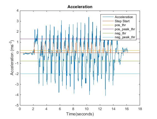
Figure 4.1: Detected steps by FSM algorithm with the acceleration signal and the threshold values for a walk with 20 steps.
Total accuracy is directly affected by the number of steps in the walk for both INS and SHS techniques. Hence the accurate detection of steps is important in these applications. Acceleration signals acquired in this phase were analyzed individually for determination of threshold values, which were then averaged to reach the final values for the test phase. In this process, the lower positive threshold ( “Thr” according to FSM algorithm) was carefully selected to be a lower value, since it mainly determines the start of a step. Detection and the threshold values are shown in figure 4.1 for a walk of 20 steps.
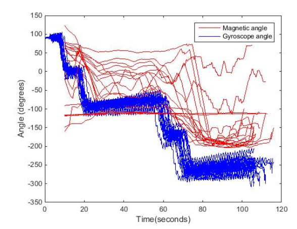
Figure 4.8: Low pass filtered angle calculated from magnetic field measurements along with the angle calculated by the gyroscope showing irregular measurements due to local distortions.
DISCUSSION AND FUTURE WORK
Indoor localization and tracking systems are currently an active research area because of its importance as a critical context in future context aware applications. Current systems for smartphone based indoor tracking are dominated by fingerprinting systems and SHS based dead reckoning systems. Feasibility of INS based dead reckoning approach was explored in this thesis.
Competitive results were observed by the proposed INS based system compared to SHS approach. Error percentage was 4.3% ( ± 3.3%) and 6.0% ( ± 3.7%) for proposed and SHS respectively in experiments of walks consisted of different paths and individuals. Also it can be observed from figure 4.14 that proposed system resulted with smaller average error and standard deviation compared to SHS approach always in all experiment categories.
A correction percentage less than 5% is required and sufficient for correction of velocity from the model for improved accuracy. Gaussian velocity model resulted in higher accuracy than other two models which is due to its flexibility in matching the actual velocity curve. Although diverse walking experiments were utilized to demonstrate the performance of the proposed method, limitations and further development steps are discussed below.
Source: Western University
Author: Rasika Lakmal Hettiarachchige Don